32x16 RGB LED display scan question

Hi ,

I have an JS Industrial Ltd. (China) fulI color 16*32 P10 LED display. This is 1/4 scan rate. I tried with Adafruit Arduino library and sample program (with Uno) , but not work properly. For example , if I want only 1 pixel to lighting , then duplicate, shift by 16 horizontal and shift vertical 4.
For text completely confused the picture.

My LED matrix has 1/4 scan rate and Adafruit panel 1/8 ? This is the problem ??
If yes , know where you can rewrite this scan rate in library ? (RGB matrix panel master or GFX master or other ... ? )

Please help me ...

THX
Ernoe

You can just try simple shift out codes written here to check your display..

//**************************************************************//
// Following codes simply shifts out data for 16x32 LED matrix.
//****************************************************************
int LP = 8;            // Latch Pin
int ClkP = 12;           // Clock Pin
int R1P = 11;          // R1 Pin
int B1P = 10;          // B1 Pin
int G1P = 9;           // G1 Pin 
int R2P = 7;           // R2 Pin
int B2P = 6;           // B2 Pin
int G2P = 5;           // G2 Pin
int AP = 2;            // A Pin
int BP = 3;            // B Pin
int CP = 4;            // C Pin
int OEP = 14;          // OE Pin
int row = 0;

void setup() {
//set pins to output so you can control the shift register
pinMode(LP, OUTPUT);
pinMode(ClkP, OUTPUT);
pinMode(R1P, OUTPUT);
pinMode(B1P, OUTPUT);
pinMode(G1P, OUTPUT);
pinMode(R2P, OUTPUT);
pinMode(B2P, OUTPUT);
pinMode(G2P, OUTPUT);
pinMode(AP,OUTPUT);
pinMode(BP,OUTPUT);
pinMode(CP,OUTPUT);
pinMode(OEP,OUTPUT);
pinMode(13,OUTPUT);
digitalWrite(2, LOW);
digitalWrite(3, LOW);
digitalWrite(4, LOW);
digitalWrite(14, LOW);
digitalWrite(13, LOW);
row=0;
}
void loop() {
digitalWrite(OEP, HIGH);
digitalWrite(LP, HIGH);
for(row=0; row<8; row++){
digitalWrite(AP, !!(row & B00000001));
digitalWrite(BP, !!(row & B00000010));
digitalWrite(CP, !!(row & B00000100));
digitalWrite(OEP, LOW);
digitalWrite(LP, LOW);
shiftOut1(R1P, B1P, G1P, R2P, B2P, G2P, ClkP);
}
}

void shiftOut1(uint8_t R1P1, uint8_t B1P1, uint8_t G1P1, uint8_t R2P1, uint8_t B2P1, uint8_t G2P1, uint8_t ClkP1)
{
     uint8_t i;

     for (i = 0; i < 32; i++)  {
                 digitalWrite(R1P1, 0);
                 digitalWrite(B1P1, 1);
                 digitalWrite(G1P1, 0);
                 digitalWrite(R2P1, 1);
                 digitalWrite(B2P1, 0);
                 digitalWrite(G2P1, 0);
                 digitalWrite(ClkP1, HIGH);
                 digitalWrite(ClkP1, LOW);
                                             
     }
}

Not sure if this is exactly the same board but it seems that it is pretty standard. You might want to check out 32x16 Red Dot Matrix Display | Freetronics.

It has demo code and instructions on how to connect it to your Arduino.

If you use it and it works post back here to let others know that it functioned with your display.

Thank You pshodasara ,

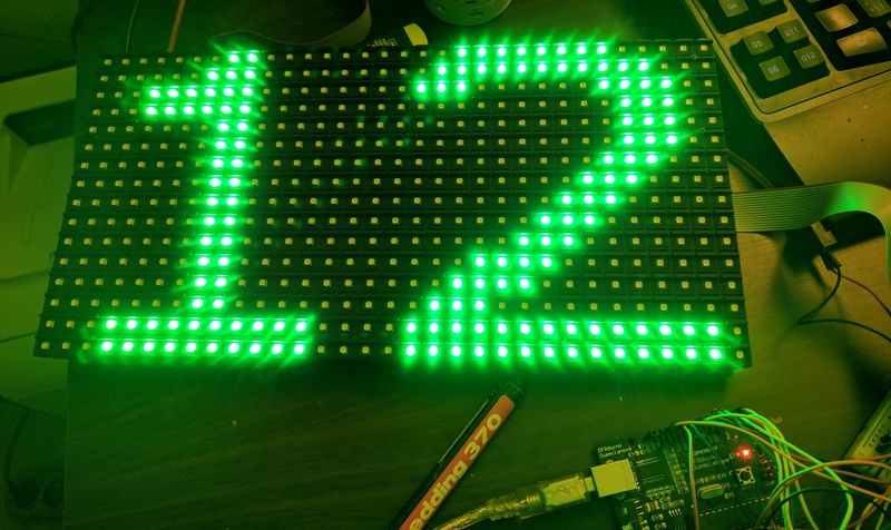
I upload Your code , and I got one half full blue and one half full red display , divided horizontally :frowning:

Therefore I insert an 100msec delay cycle (for slowly motion) to loop end , and result visible in following video :

The pins connections changed , but wired are ok.

//**************************************************************//
// Following codes simply shifts out data for 16x32 LED matrix.
//****************************************************************
int LP = A3; // Latch Pin 8
int ClkP = 8; // Clock Pin 12
int R1P = 2; // R1 Pin 11
int B1P = 4; // B1 Pin 10
int G1P = 3; // G1 Pin 9
int R2P = 5; // R2 Pin 7
int B2P = 7; // B2 Pin 6
int G2P = 6; // G2 Pin 5
int AP = A0; // A Pin 2
int BP = A1; // B Pin 3
int CP = A2; // C Pin 4
int OEP = 9; // OE Pin 14
int row = 0;

void setup() {
//set pins to output so you can control the shift register
pinMode(LP, OUTPUT);
pinMode(ClkP, OUTPUT);
pinMode(R1P, OUTPUT);
pinMode(B1P, OUTPUT);
pinMode(G1P, OUTPUT);
pinMode(R2P, OUTPUT);
pinMode(B2P, OUTPUT);
pinMode(G2P, OUTPUT);
pinMode(AP,OUTPUT);
pinMode(BP,OUTPUT);
pinMode(CP,OUTPUT);
pinMode(OEP,OUTPUT);
pinMode(13,OUTPUT);
digitalWrite(AP, LOW);
digitalWrite(BP, LOW);
digitalWrite(CP, LOW);
digitalWrite(OEP, LOW);
digitalWrite(LP, LOW);
row=0;
}
void loop() {
digitalWrite(OEP, HIGH);
digitalWrite(LP, HIGH);
for(row=0; row<8; row++){
digitalWrite(AP, !!(row & B00000001));
digitalWrite(BP, !!(row & B00000010));
digitalWrite(CP, !!(row & B00000100));
digitalWrite(OEP, LOW);
digitalWrite(13, LOW);
shiftOut1(R1P, B1P, G1P, R2P, B2P, G2P, ClkP);
}
}

void shiftOut1(uint8_t R1P1, uint8_t B1P1, uint8_t G1P1, uint8_t R2P1, uint8_t B2P1, uint8_t G2P1, uint8_t ClkP1)
{
uint8_t i;

for (i = 0; i < 32; i++) {
digitalWrite(R1P1, 0);
digitalWrite(B1P1, 1);
digitalWrite(G1P1, 0);
digitalWrite(R2P1, 1);
digitalWrite(B2P1, 0);
digitalWrite(G2P1, 0);
digitalWrite(ClkP1, HIGH);
digitalWrite(ClkP1, LOW);
delay(100);

}
}


Maybe faultly the display , and other idea ?

Thank You
nernoe

Hi Milamber ,

the Freetronics display only red ,(with different pinout) and sample prog not works with my display :frowning:

THX
nernoe

@nernoi,
If it shows upper half blue and lower half red than your display is perfectly OK. But as it is 1/4 scan display, you will be required to modify codes in Ada-fruit RGB matrix panel library.

for (i = 0; i < 32; i++)  {
                 digitalWrite(R1P1, 0);
                 digitalWrite(B1P1, 1);
                 digitalWrite(G1P1, 0);
                 digitalWrite(R2P1, 1);
                 digitalWrite(B2P1, 0);
                 digitalWrite(G2P1, 0);
                 digitalWrite(ClkP1, HIGH);
                 digitalWrite(ClkP1, LOW);

In above simple example, shiftout 64 bits at a time instead of 32 bits. (put i<64;)
You can change the value of R1P1(Red LED upper half), B1P1(Blue LED upper half), G1P1(Green LED upper half), R2P1(Red LED lower half), B2P1(Blue LED lower half) and G2P1(Green LED lower half) to produce different colors for test purpose.

Thanks ,

useful information for your :slight_smile: I play with colors and colors are OK.
But i do not understand, why 2 line go paralell in the upper and also paralell 2 line in the lower half of the display.

In addition, the Latch pin does not matter if I connect fix low or fix high level, the display does the same thing as in the My video.
(The pin is good connect in display side)

????

THX

But i do not understand, why 2 line go paralell in the upper and also paralell 2 line in the lower half of the display.

This is because it is 1/4 scan display.
Adafruit display is 1/8 scan. Means 512/8=64 LEDs (2 Lines, one upper half and one lower half can be ON at a time). In your display is 1/4 scan. Means 512/4=128 LEDs (4 Lines, two upper half and two lower half can be ON at a time).

I have prepared a sample program to try. Please try it and let me know what happens?

//**************************************************************//
// Following codes simply shifts out data for 16x32 LED matrix.
//****************************************************************
uint64_t row1[16];
uint64_t temp;
int LP = 30;            // Latch Pin
int ClkP = 32;           // Clock Pin
int R1P = 25;          // R1 Pin
int B1P = 27;          // B1 Pin
int G1P = 26;           // G1 Pin 
int R2P = 28;           // R2 Pin
int B2P = 15;           // B2 Pin
int G2P = 14;           // G2 Pin
int AP = 29;            // A Pin
int BP = 11;            // B Pin
int CP = 12;            // C Pin
int OEP = 13;          // OE Pin
int row = 0;
uint8_t i;

void setup() {
//set pins to output so you can control the shift register
pinMode(LP, OUTPUT);
pinMode(ClkP, OUTPUT);
pinMode(R1P, OUTPUT);
pinMode(B1P, OUTPUT);
pinMode(G1P, OUTPUT);
pinMode(R2P, OUTPUT);
pinMode(B2P, OUTPUT);
pinMode(G2P, OUTPUT);
pinMode(AP,OUTPUT);
pinMode(BP,OUTPUT);
pinMode(CP,OUTPUT);
pinMode(OEP,OUTPUT);

digitalWrite(AP, LOW);
digitalWrite(BP, LOW);
digitalWrite(CP, LOW);
digitalWrite(LP, LOW);
digitalWrite(OEP, LOW);
row=0;
temp = 0x0000000000000001;
row1[0] = 0x1111014010701F38;
row1[1] = 0x1112914030800144;
row1[2] = 0x38E44E7C11044204;
row1[3] = 0x0000000011E28638;
row1[4] = 0x7DE41E7C00000000;
row1[5] = 0x3944D13811E3DE10;
row1[6] = 0x5524515455145154;
row1[7] = 0x1113DE1039141138;
}

void loop() {
for(row=0; row<4; row++){
   for (i = 0; i < 64; i++)  {
      digitalWrite(B1P, !!(row1[row] & (temp << (63-i))));
      digitalWrite(R1P, 0);
      digitalWrite(G1P, 0);
      digitalWrite(B2P, !!(row1[row+4] & (temp << (63-i))));
      digitalWrite(R2P, 0);
      digitalWrite(G2P, 0);
      digitalWrite(ClkP, HIGH);
      digitalWrite(ClkP, LOW);
      }   
   digitalWrite(OEP, HIGH);
   digitalWrite(LP, HIGH);  
   digitalWrite(AP, !!(row & B00000001));
   digitalWrite(BP, !!(row & B00000010));
   digitalWrite(CP, !!(row & B00000100));
   digitalWrite(OEP, LOW);
   digitalWrite(LP, LOW);   
   }
}

Hi,

thank you . I will tray little later , after Easter :slight_smile:
But I very interested , what will be.
I will describe it....

Thx
nernoe

Above code should display Text "16x32" on upper half and "RGB" on lower half. If it does not display properly than change following values and try again.

row1[0] = 0x10701F3811110140;
row1[1] = 0x3080014411129140;
row1[2] = 0x1104420438E44E7C;
row1[3] = 0x11E2863800000000;
row1[4] = 0x000000007DE41E7C;
row1[5] = 0x11E3DE103944D138;
row1[6] = 0x5514515455245154;
row1[7] = 0x391411381113DE10;

Hí ,

I tried , and result in the attachments. (firstcode what You firstly sent).

About 10 times I verify the connections . The connections are according the Adafruit.

I about to give up .... :frowning:

THX
nernoe

secode.jpg

OK...

Hello,

I order an 1/8 scan rate display...
This is work properly :slight_smile:

Thank You for help :slight_smile:

Best regards
nernoe

Hi all

I know this is an old topic and this is my first post

I have the exact same result as the last guy and was wondering if anyone managed to get these panels working

I would like to scroll a simple Tune To 95.1FM across a panel, I have the code done but it only works of 1/8 scan rate panels and cant seem to find any information on the 1/4 scan rate panels.

any help would be much appreciated

Regards

Ted

I think I have solved problem how to show correct information on P10 RGB 16x32 panels with HUB75, 1/4 scan.

Using spreadsheet from google apps I have made structure of panel. I can simply draw everything I want by setting 1 or clearing cell values.
After each change a generated part of program (blue color) is automatically updated.

Copy those 8 lines and replace equivalent in program psghodasara has published here in this forum (post #7).
Because I have Arduino Duemillanueve (eq. Uno), I had to use different pinout:

int LP = 8; // Latch Pin
int ClkP = 12; // Clock Pin
int R1P = 11; // R1 Pin
int B1P = 10; // B1 Pin
int G1P = 9; // G1 Pin
int R2P = 7; // R2 Pin
int B2P = 6; // B2 Pin
int G2P = 5; // G2 Pin
int AP = 2; // A Pin
int BP = 3; // B Pin
int CP = 4; // C Pin
int OEP = 14; // OE Pin

Spreadsheet I have made is now shared as public and open for editing, so feel free to make changes.
Only the formula fields are protected.
As a graphics overlay I have used google drawings with transparent background. It helps to draw shapes or characters from different fonts, stretch and scale them.

Here's a link to spreadsheet: rgb - Google Sheets

Thanks a lot psghodasara and kolnier, with your code and spreadsheet I was finally able to display something readable on a cheap outdoor P10 32x16 RGB panel with 1/4 scan.
Recreating the structure of the panel must've been quite some work, nicely done!

I'd like to use the Adafruit_GFX library, but to be able to use it, RGBLEDMatrix has to be modified to use the right led/row order to match the panel structure.

It seems that RGBmatrixPanelAlternative (GitHub - zidik/LedMatrix16x32-Alternative: Library for driving cheap chinese 16x32 LED matrices.) might work with 1/4 scan panels, so if the transformation can be added to it, that might work.

Is there a math/byte wizard who could write a transformation function based on the layout as specified in the spreadsheet by kolnier, which can be used with RGBmatrixPanelAlternative (in drawPixel or updateDisplay?)?

Edit: I've made an overview of how the rows are constructed:

Is there a way to make this work with Adafruit_GFX or DMD maybe?

Edit2: I've probably got the logic reversed. If the row is in HEX: 0x0000000000000003 then leds '2' and '1' of ROW 0 of the 15th byte are lit. Should the schematic point in the other direction (low bits first) ?

1 Like

I've modified the RGBmatrixpanel.cpp and .h to be able to use Adafruit_GFX with 1/4 scan panels now:

https://forum.arduino.cc/index.php?topic=503416.0

Ruud:
I've modified the RGBmatrixpanel.cpp and .h to be able to use Adafruit_GFX with 1/4 scan panels now:

P10 32x16 LED panel 1/4 scan now works with Adafruit_GFX - LEDs and Multiplexing - Arduino Forum

That didn't work with my p10 32*32 1/4 scan panel

still looking for a solution for this one although it worked fine with 16*32 panel from the same type.

kolnier:
I think I have solved problem how to show correct information on P10 RGB 16x32 panels with HUB75, 1/4 scan.

Using spreadsheet from google apps I have made structure of panel. I can simply draw everything I want by setting 1 or clearing cell values.
After each change a generated part of program (blue color) is automatically updated.

Copy those 8 lines and replace equivalent in program psghodasara has published here in this forum (post #7).
Because I have Arduino Duemillanueve (eq. Uno), I had to use different pinout:

int LP = 8; // Latch Pin
int ClkP = 12; // Clock Pin
int R1P = 11; // R1 Pin
int B1P = 10; // B1 Pin
int G1P = 9; // G1 Pin
int R2P = 7; // R2 Pin
int B2P = 6; // B2 Pin
int G2P = 5; // G2 Pin
int AP = 2; // A Pin
int BP = 3; // B Pin
int CP = 4; // C Pin
int OEP = 14; // OE Pin

Spreadsheet I have made is now shared as public and open for editing, so feel free to make changes.
Only the formula fields are protected.
As a graphics overlay I have used google drawings with transparent background. It helps to draw shapes or characters from different fonts, stretch and scale them.

Here's a link to spreadsheet: rgb - Google Sheets

Please check this to the end here...

"I think I have solved problem how to show correct information on P10 RGB 16x32 panels with HUB75, 1/4 scan.

Using spreadsheet from google apps I have made structure of panel. I can simply draw everything I want by setting 1 or clearing cell values.
After each change a generated part of program (blue color) is automatically updated."

I did it and it works with my display but i am using two display (32x16) and i made changes in code but it not work properly so please if anyone made such code will help me