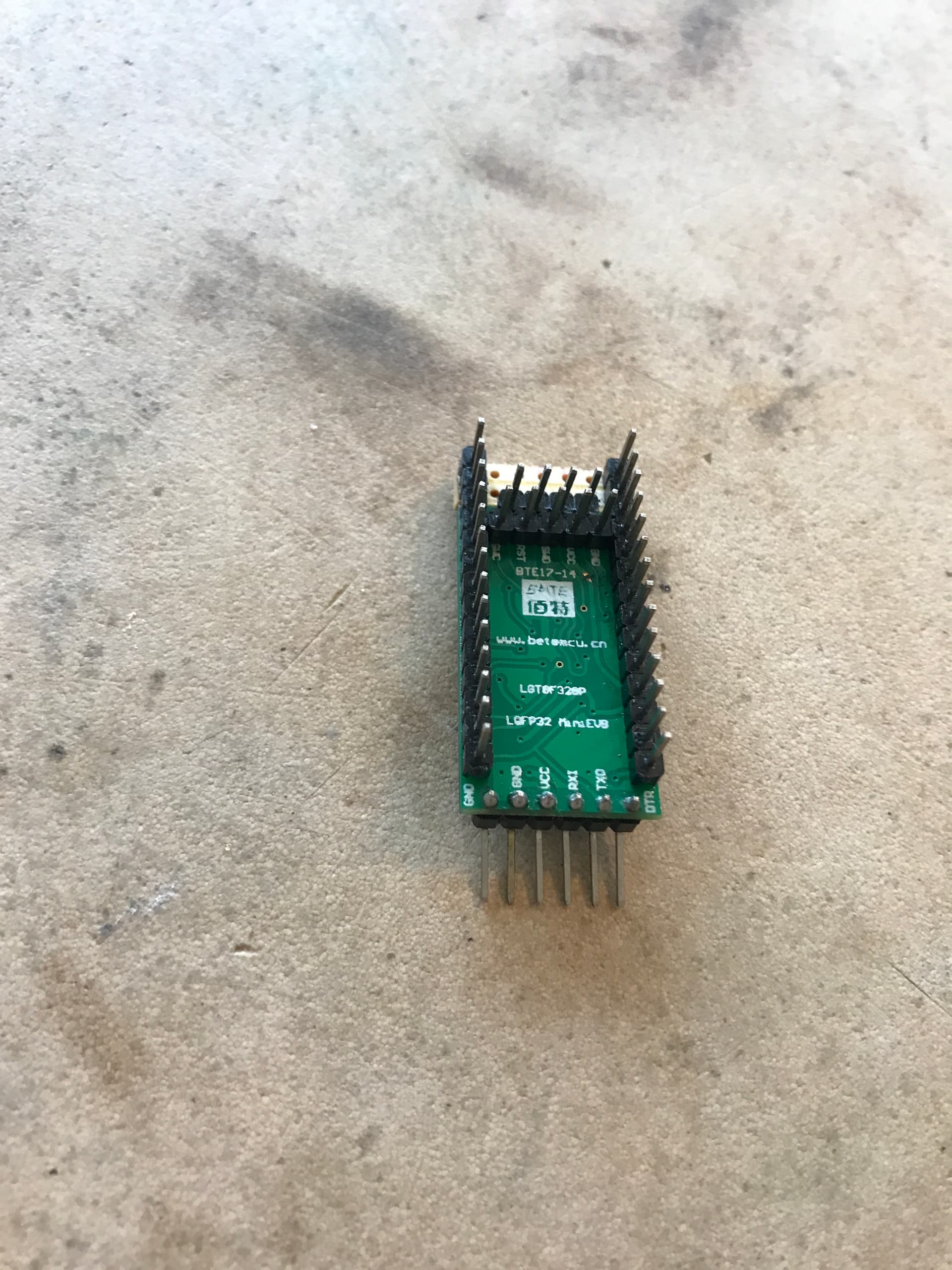
I have a project and needed more i/o than available on a PROMINI so I turned to an LGT8F328P. The board has more i/o than the PROMINI. However, even with this board I found I needed a few more. Rather than turn to another board, I noticed there were 4 unused pins according to the documentation. Hence I created an addon board and wired the pins to the i/o and hey presto, I have 4 more! This mod retains the original board funtionality which I like.
I post this to show my modification. It works well for me. I am interested in anyone who has done something similar - there may be a better way.


I found I was unable to use SWC and SWD pins for I/O. They seem to be reserved for debugging. The documentation stated this can be disabled with MCUSR register bit 7 SWDD (written twice). Hence I attach my version of blink which seems to work. This enables 2 more pins for I/O.
/*
  LGT8328P Blink SWC and SWD
*/

byte data;

// the setup function runs once when you press reset or power the board
void setup() {
  MCUSR |= (1 << 7);
  MCUSR |= (1 << 7);
  DDRE |= B00000101;
  pinMode(LED_BUILTIN, OUTPUT);
  data = MCUSR;
  Serial.begin(115200);
  Serial.println("begin");
  Serial.println(data, BIN);
}

// the loop function runs over and over again forever
void loop() {
  digitalWrite(LED_BUILTIN, HIGH);   // turn the LED on (HIGH is the voltage level)
  PORTE |= B00000101;   // turn the LED on (HIGH is the voltage level)
  delay(1000);                       // wait for a second
  digitalWrite(LED_BUILTIN, LOW);    // turn the LED off by making the voltage LOW
  PORTE &= B11111010;    // turn the LED off by making the voltage LOW
  delay(1000);
}
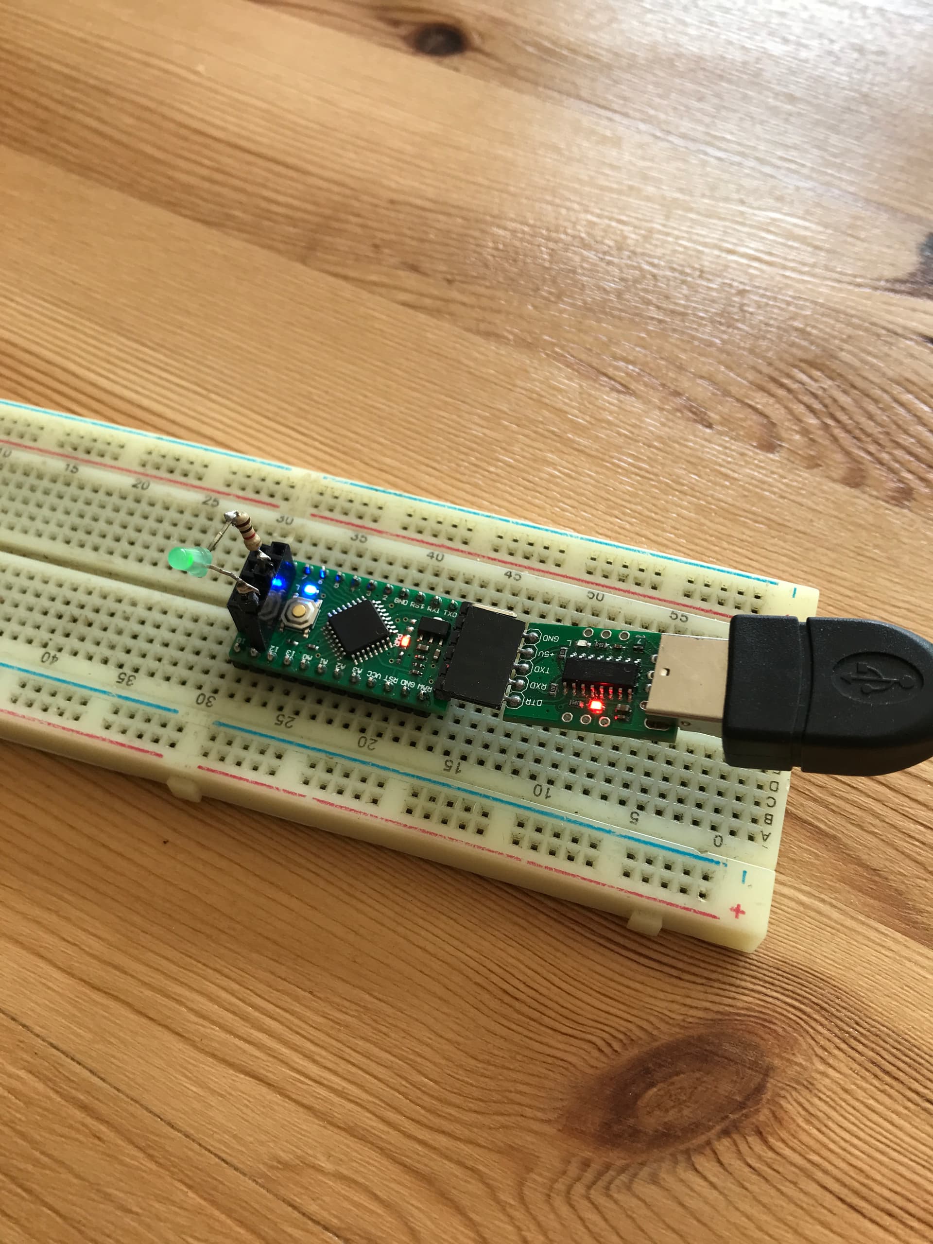
The AVREF pin (which has alternative functionality) is the last pin not available. I chose to cut the track to the Vcc pin on the end of the board - Vcc is still on the side of the board. This makes the pin available for another purpose. I unsoldered the small capacitor and made a link to the pin. Hence, with these modifications, I have all the pins wired and usable.

Hi, thanks for sharing !
the way you added 2 additional rows is that smart !
thoughts :
- there is a (big) nano style board witch exposes all the pins of the 48 pins variant MCU
- one can cut the tracks of the RST pins , in order to reuse them for two additional IOs
- one might toggle the PORTE pins by writing a 1 to the PINE register
- they are purple boards , witch have crystals , if one need better than 1% precision