My wavgat uno port 5, 6 dead,and regulator 3.3v is 3.9v.I am sure mcu damadged due to some reason. I see somebody changed LGT8F328P by atmega328 and working.I do the same thing, and load boot-loader success. But try usb load a test blink sketch failed. Compare LGT8F328P and atmega328,Vcc connection pin 4,6,18 and Gnd pin 3,5,21 different,measure on board 3,5,21 connected to Gnd, 4,6 connected to 3.3V,18 is unknow. Since LGT8F328P 18 is not AVcc pin but match arduino board must be hang(unused),so replace by real atmega328,I try jump 18 to Vcc.After connect 18 to 4,6 together, re-load sketch blink by usb convert upload done success. Actually,before connect 18 pin to Vcc, I test that pin voltage is 3.1V and 4,6 pin is 3.9V on power and when I jump 3.3V bypass to 5V, 18 pin is 4.2 V without connect directly to 3.3 or 5v, download program by Usb success already.I am not sure other gay's board connect 5v to LGT8F328P or 3.3v, but mine must have to connect pin 18 to power(4,6,18) or 5v supply(18 unconnected to 4, 6). Now my wavgat uno become real clone Arduino uno.In IDE choose board arduino uno/mini/nano instead of Wavgat uno or lgt8f328 relative.
Two option:1, solder jump wire on atmega328 pin 4 or 6 to 18 since the pcb pad no connection; 2, jump wire 3.3v to 5V bypass as long as you never use 3.3v supply to output purpose(my board 3.3 regulator dead, choose it no solder).
I paste other one similar topic,thanks for that.


I don't understand your story about the 3.3volt supply in post#1.
But note that that 3.3V supply is also used as reference voltage to switch a USB backflow protection mosfet on/off in case you power the Uno externally via V-in or the DC socket.
Your board seems to be missing the 8-pin LM358V chip to accomodate that.
If so, then it also doesn't have the pin13 LED buffering that that chip also does.
Maybe best to use that board as a door-stop.
Leo..
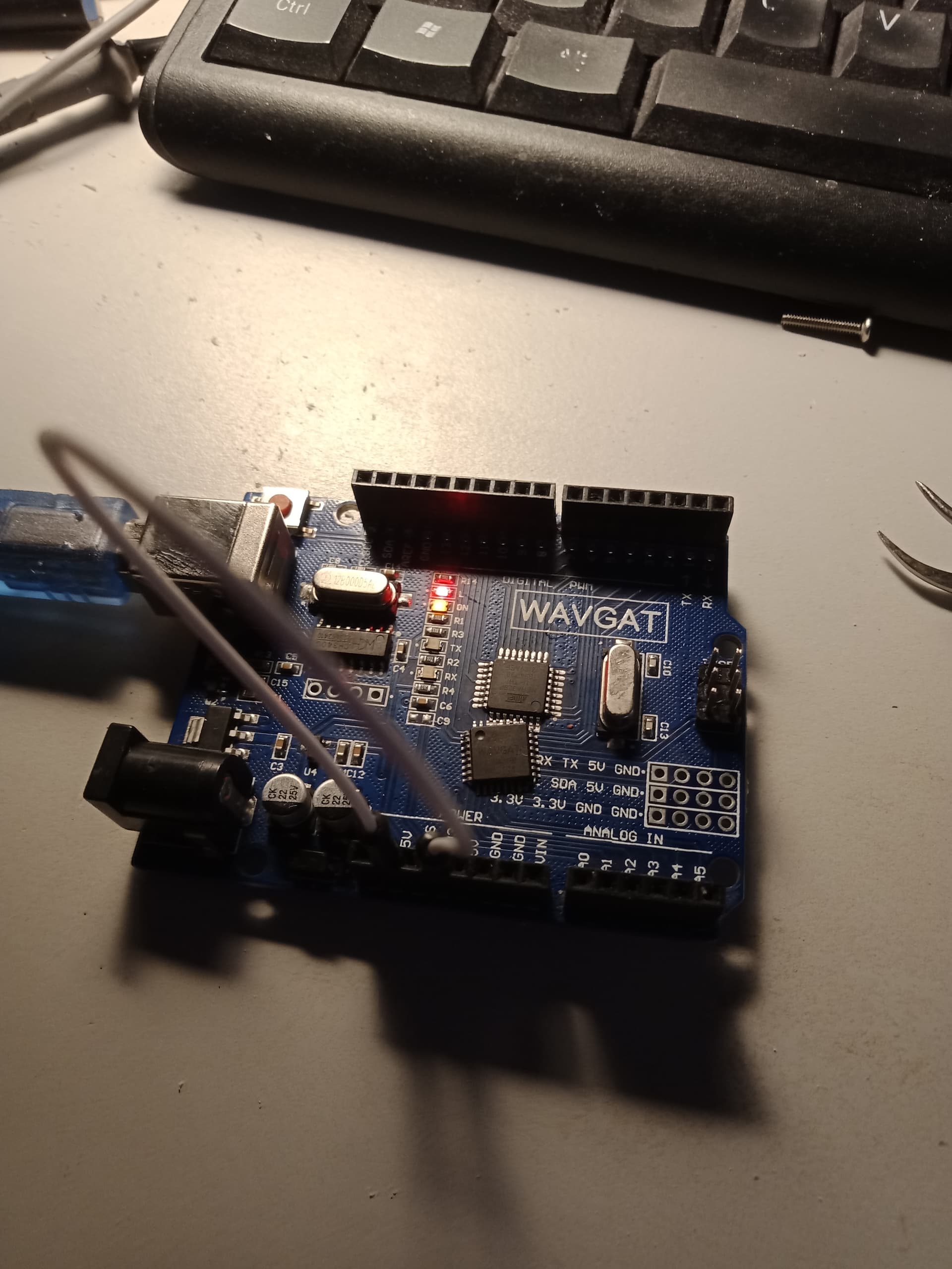
Wavgat uno uses 3.3V supply lgt8f328(mark AVGA328) and Arduino uno uses 5v supply atmega328. LGT8F328 pin 18 is not connected to Vcc.I replace atmega328 on Wavgat board not working though burn boot-loader and ISP load program ok. Experiment confirms when I change 5v to supply atmega328, every thing ok although without connecting pin 18 to Vcc. Lm358 is used to switch Jack power supply and drive L-led, , omit on Wavgat uno R3 , it doesn't make sense,attach picture red led on/off means blink working.Since I don't use Jack power or Vin pin, no solder, no 3.3v needed.Only jump 3.3 to 5v let board work enough.
If i solder wire pin18 together with pin4,6, keep 3.3v supply atmega328 still ok. Say again wavgat uno and relative board only compatible Arduino, not total match. Once replace LGT8F328 with Atmega328p, I believe I let wavgat uno total match Arduino, this can solve Arduino program compatible clone trouble for edit layman like me.
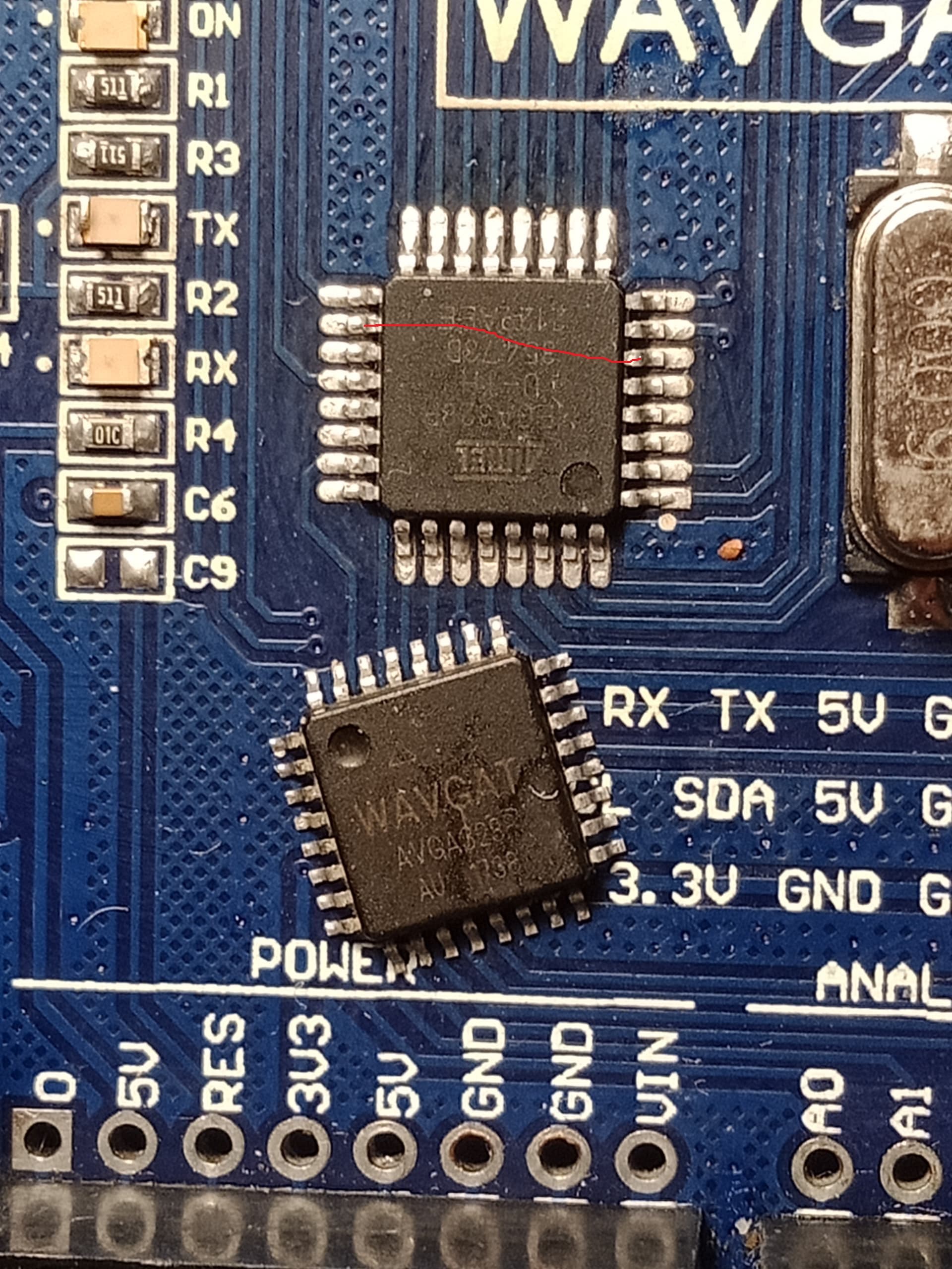
you can jump wire below red drawing, for I/O port 3.3v, keep jack power usage
LGT8F328 can run 16mhz frequency at 1.8-5.5V.Atmega328p can run 16mhz at 3.3V in most post claim, but datasheet no guaranty. Guaranty run 16mhz should be up 3.8v. So that is why Arduino mini has two version: 5v/16mhz and 3.3v/8mhz
I am still wondering how Mamejay said the board can run directly after replace atmega328. The board only a little bit different from mine. Apparently only USB micro? My board was bought in 2018

It could be that Wavgat have used a variety of "clones" of the original ATmega328P and printed the chip with "WAVGAT".
The LGT8F328P cannot be used directly with the Arduino Uno board package in the IDE or things start going wrong immediately (timing issues etc.). Suppliers who sell boards with the LGT8F328P chip usually talk about one of the following board packages LGTMCU/Larduino_HSP, nulllaborg/arduino_nulllab, emakefun etc. There is, incidentally, what seems to be a well respected LGT8F328P board package here which I have used in one simple project: GitHub - dbuezas/lgt8fx: Board Package for Logic Green LGT8F328P LGT8F328D and LGT8F88D
If the Wavgat board performed more or less OK together with the standard Arduino Uno board package then the chances are that chip was not a relabeled LGT8F328P.
This is the LGT8F328P pinout from https://wolles-elektronikkiste.de/en/lgt8f328p-lqfp32-boards

And this is the ATmega328P:

Clearly there are some differences.
Incidentally, the soldering of the marked row of pins seems not as good as the rest:
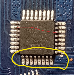
6v6gt thanks for your explanation. My replaced part soldering OK, maybe camera shoot shade different. I said before, Wavgat board micro-controller 3,5, 21 pin connect to Gnd, same as Arduinon uno. Wavgat 4, 6 pin is connected to Vcc= 3.3v and 18 pin is float, both are different from Arduino. Atmega328 can work at 5v even 18 pin float, but 18 pin must connect to Vcc if I try to work at 3.3v duing my experiment. Mamejay post doesn’t mention anymore. Anyway, I test digital output by shift D13 to other I/O pin OK(re-define blink sketch led pin). Not done analog test. 18 Pin is AVcc on atmega328, floating may affect analog function? I don’t know.
I have known Lgt8f nano and mini are different from Wavgat uno, pin18(SWC), 21(SWD) use special for ISP program? not same as real arduino Mosi/Miso