Linear laser encoder

Good day. I purchased a linear encoder.


Trying to test it, I assembled the following circuit.

I wrote the following code

int PinA = 12;
int PinB = 2;
int val = 0;
int val2 = 0;

void setup(void) {
 Serial.begin(9600);
 pinMode(PinA, INPUT_PULLUP);
 pinMode(PinB, INPUT_PULLUP);
}

void loop(void) {
 val = digitalRead(PinA); 
 val2 = digitalRead(PinB); 
 
 Serial.print("A value: ");
 Serial.print(val);
 
Serial.print("\tB value: ");
 Serial.println(val2);
}

I get the following result
image
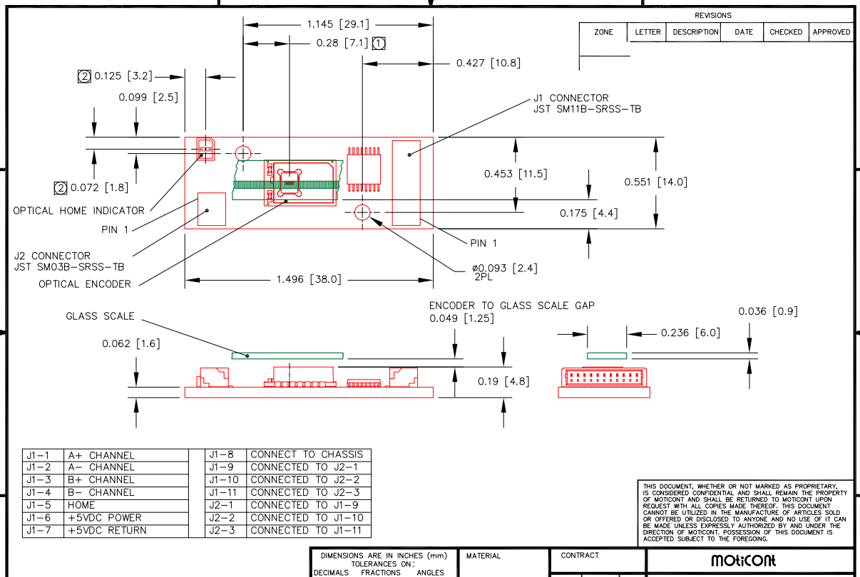
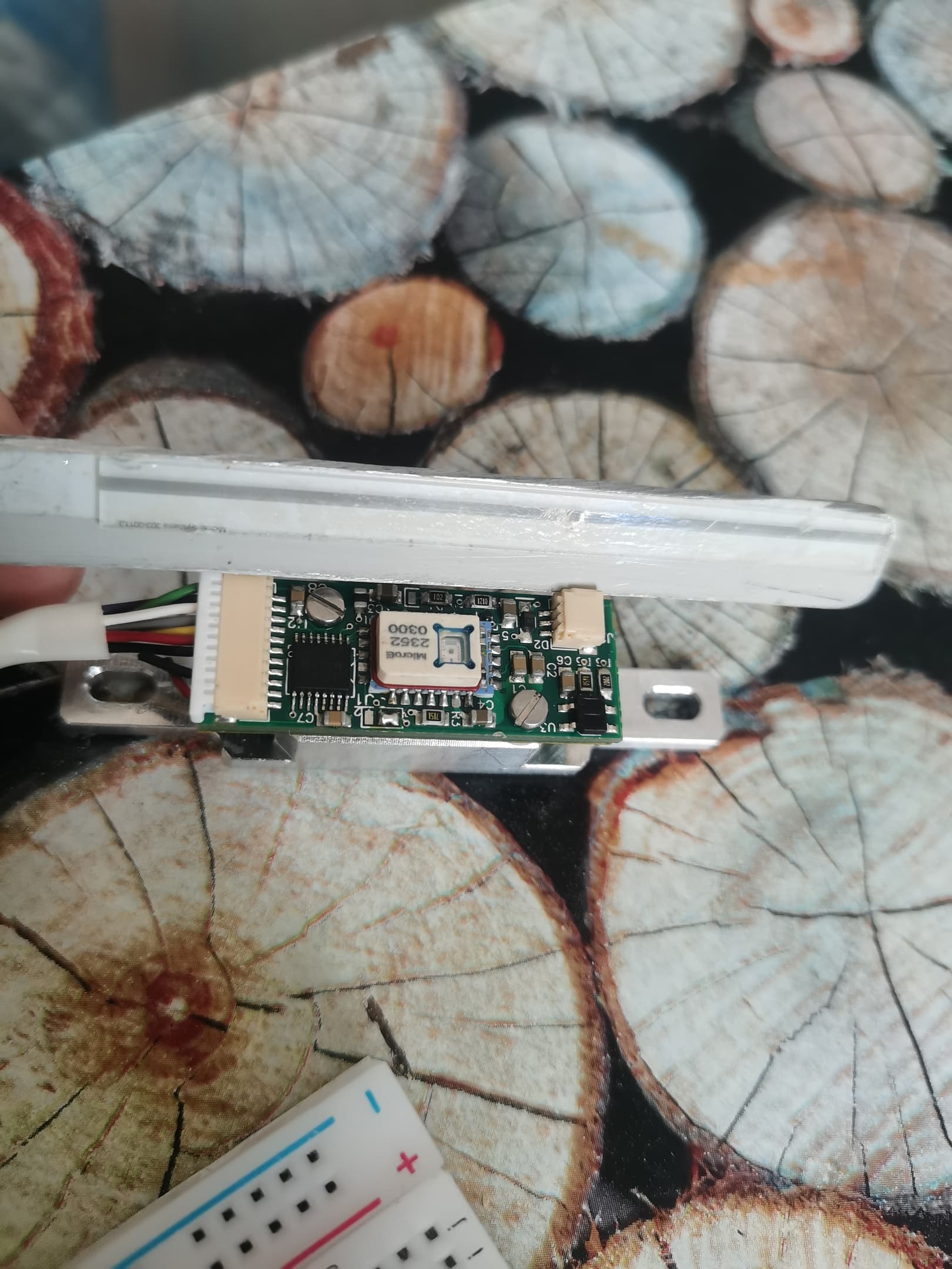
Channel B reacts to changes and changes 1 to 0 when touched by the laser. Channel A does not react to anything, it constantly hangs at 0. I think maybe I screwed up somewhere in the connection diagram. Does anyone have an idea why channel A does not work? And what is this 5 channel that says that it is a reference channel, no matter how I connect it to + and -, it does not affect anything.

Please post a link to the encoder data sheet or product page, and a new schematic diagram, clearly showing all the relevant pin numbers. Hand drawn is fine.

Drawing shows a connection to pin 13, listing shows connection to pin 12.  What's up wit dat?

There was a typo in the diagram, I have now redrawn it to the correct one.


Last diagramm


Last diagramm

The web page you linked to says that the outputs are TTL Differential Quadrature Outputs. You might want to explore this.

I'm not sure whether you should be grounding the A- and B- outputs, they look like they are complementary to the A+ and B+ outputs, for connecting to RS485 - TTL converters.

The documentation provide by the seller is poor.

1 Like

Connected A- (А2) and B- (Π’2) to the input.

int PinA1 = 12;
int PinB1 = 2;
int PinA2 = 13;
int PinB2 = 4;
int val = 0;
int val2 = 0;
int val01 = 0;
int val02 = 0;

void setup(void) {
 Serial.begin(9600);
 pinMode(PinA1, INPUT_PULLUP);
 pinMode(PinB1, INPUT_PULLUP);
 pinMode(PinA2, INPUT_PULLUP);
 pinMode(PinB2, INPUT_PULLUP);
}

void loop(void) {
 val = digitalRead(PinA1); 
 val2 = digitalRead(PinB1); 
 val01 = digitalRead(PinA2); 
 val02 = digitalRead(PinB2); 
 
 Serial.print("A1 value: ");
 Serial.print(val);

Serial.print("\tA2 value: ");
 Serial.print(val01);
 
 Serial.print("\tB1 value: ");
 Serial.print(val2);

Serial.print("\tB2 value: ");
 Serial.print(val02);

}

got it
image
B1 (B+) and B2 (B-) change their value when touched by a laser. But A1(A+) and A2(A-) are const = 0;

Hi, @grehtryesek785

Disconnect the HOME pin from gnd as well.

Are you using appropriate linear scale to test the encoder?

Can you please post some images of your project with the linear scale fitted?

Tom... :smiley: :+1: :coffee: :australia:

Yes, A- and B- are just inverted signals A+ and B+. Most likely, when connecting them to ground, I burned channel A. That's why it refuses to work.

Most possibly not, as when the output BJTs would be turned ON, they would short the relevant output to gnd anyway, otherwise the equivalent of open circuit.

Tom.. :smiley: :+1: :coffee: :australia:


I just move the ruler back and forth

Hi,
Is that linear scale still in its plastic bag?
Have you moved the laser head along the grey bars on the slider?

Tom... :smiley: :+1: :coffee: :australia:

The magnetic ruler is glued to a wooden board. Yes, the sensor moved along the gray strip.

It was definitely a mistake to connect the A-, B- differential signals to ground, but whether that damaged the outputs depends on their internal structure.

For example, if the outputs are open collector/drain and are intended to be used with external pullup resistors, then no problem. If the outputs are totem pole, then they could well be damaged.

The documentation is nearly hopeless, which I do not expect for such an expensive item, so your best option is to test the encoder on the bench, using an oscilloscope and other test equipment to examine the output signals.

This topic was automatically closed 180 days after the last reply. New replies are no longer allowed.