I have used Arduino's 0-5V PWM for 0-10V generation using LM358.
I have attached circuit diagram below. I have used +12v, 2A power supply and gave +12v to 8th pin of LM358.
When I'm trying to measure voltage at LM358 output without Load, It works fine. But when I attach load (Small DC motor) it gives 0V on output.
Likely your motor requirements exceed the capability of the LM358.
The output of the LM358 is limited to between 20 and 40 ma. Do you know what your motor requires?
I know the details are difficult to get your head around when you are starting out, however you should try to collect the requirements and capabilities of each part in your project. It won't be too long before it becomes 2nd nature.
Although you could (possibly) add some transistors or MOSFETs to boost the current capability of the LM358, A linear amplifier isn't required to boost PWM voltage/current and you can skip the op-amp. i.e. A linear amplifier with a gain of 2 would give you'd get 2V out with 1V in, but PWM only switches between zero and 5V.
Either one of those can drive your motor (with PWM to get variable speed). You just need to supply the 10 or 12V. Make sure the transistors/MOSFETs can handle the current required by the motor, and make sure power supply can provide it.
deep:
I have used Arduino's 0-5V PWM for 0-10V generation using LM358.
I have attached circuit diagram below. I have used +12v, 2A power supply and gave +12v to 8th pin of LM358.
When I'm trying to measure voltage at LM358 output without Load, It works fine. But when I attach load (Small DC motor) it gives 0V on output.
Please guide what's the problem?
The LM-358 can source 40 milliamps and sink 50 milliamps. I'll bet dollars to donuts that your DC motor draws a LOT more than 40 milliamps, hence the op-amp output throws it's hand up and quits.
You need something like an emitter follower after the op-amp output to boost the output current (and be sure your negative feedback then goes to the transistor emitter to keep the loop closed).
Thanks for the reply. Actually requirement is to operate Valve actuator (Controlled by 0-10V DC).
JohnRob:
Likely your motor requirements exceed the capability of the LM358.
The output of the LM358 is limited to between 20 and 40 ma. Do you know what your motor requires?
I know the details are difficult to get your head around when you are starting out, however you should try to collect the requirements and capabilities of each part in your project. It won't be too long before it becomes 2nd nature.
deep:
But when I attach load (Small DC motor) it gives 0V on output.
Please guide what's the problem?
A small DC motor is a massive load, perhaps upto 1A, completely and utterly beyond any standard
opamp.
The LM358 is also a very very slow opamp, losing full output-voltage swing from 5kHz or less,
so only useful for low frequency analog signals (not even good for most audio), nowhere near
fast enough for digital waveforms like PWM unless really slow. Why are you not low-pass filtering
the PWM anyway?
What are you actually trying to drive with your 0..10V signal?
MarkT:
A small DC motor is a massive load, perhaps upto 1A, completely and utterly beyond any standard
opamp.
The LM358 is also a very very slow opamp, losing full output-voltage swing from 5kHz or less,
so only useful for low frequency analog signals (not even good for most audio), nowhere near
fast enough for digital waveforms like PWM unless really slow. Why are you not low-pass filtering
the PWM anyway?
What are you actually trying to drive with your 0..10V signal?
But that could be anything. Details please of the particular valve actuator you are meaning... Link to datasheet
is preferred way to impart such information.
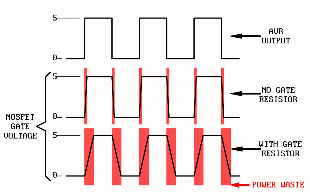
Good circuit, but I would do away with the 470 ohm gate resistor. All that will do is, due to the mosfet's gate capacitance (made worse by the Miller effect), is slow down the switching time and cause the fet to stay longer in the "power wasting, heat producing" linear region. No need for it, and since the AVR output are also mosfets, their inherent on resistance (between drain and source) will easily absorb the "few microseconds at most" overcurrent spike caused by the AVR output forcible charging (or discharging) the gate. Remember, a mosfet conducting is equivalent to a resistor, and that resistor will not overheat in such a short time.
This sketch explains it. Of course, the waveforms depicted are linear when in fact they should be typical R/C charge/discharge curves, but the idea is not lost without the proper curve shape (and it would have been a pain to draw it).
(click image for full size)
You can also see that since the power wasted area remains constant, the total waste is proportional to thr PWM frequency. If the frequency were high enough, the power wasted areas would touch (or even OVERLAP!). Not a good way to use a mosfet.
TomGeorge:
Hi,
Replace the motor in the circuit I posted with your valve actuator.
By the way, what software did you use to draw that schematic? I used to use (a long time ago) OrCad for MS-DOS and it was great... simple and easy to use. Now, with Eagle CAD, making a simple schematic is a royal pain. I want a simple schematic drawing program... no frills, no auto router... just something to place pre-drawn passives and chips, then draw lines between them. That's all I need.
Good circuit, but I would do away with the 470 ohm gate resistor.
Do so if you wish, but this is bad advice.
The gate capacitance acts as a temporary short circuit, and the drive current will exceed the output pin specification, damaging the Arduino. Always use a series resistor in such an application, 130 Ohms minimum for a 5V circuit.
jremington:
Do so if you wish, but this is bad advice.
The gate capacitance acts as a temporary short circuit, and the drive current will exceed the output pin specification, damaging the Arduino. Always use a series resistor in such an application, 130 Ohms minimum for a 5V circuit.
If you believe that, then you must not know how mosfets work.
krupski:
By the way, what software did you use to draw that schematic? I used to use (a long time ago) OrCad for MS-DOS and it was great... simple and easy to use. Now, with Eagle CAD, making a simple schematic is a royal pain. I want a simple schematic drawing program... no frills, no auto router... just something to place pre-drawn passives and chips, then draw lines between them. That's all I need.
N.B. I am running Debian Linux x86_64.
ExpressPCB but I'm not sure if they have a Linux version
Its is excellent to install, not associated junk, or any sneaky unwanted apps trying to install as well
The only thing is if you use the PCB design, it will not produce a gerber file.
Tom...
krupski:
If you believe that, then you must not know how mosfets work.
We don't believe it, we calculate it, driving a large capacitive load without a series resistor definitely
exceeds the absolute maximum rating of 40mA for an output pin. However there is no more
detailed information in the datasheet - is that a peak rating or a continuous rating? In the absence
of specific information you just assume its a never-exceed value, and adding a 150 ohm resistor
is the safe thing to do.
It may be the case that the pin short-duration peak current absolute max rating is higher than 40mA, but
we don't have any data.
I wonder why are you so afraid of discrete MOSFETs. You say
MarkT:
driving a large capacitive load without a series resistor definitely exceeds the absolute maximum rating of 40mA
In fact driving ANY capacitive load means lot of current if you ignore parasitic resitance and inductance of wires and the chip itself. So even driving pin connected to nothing is "dangerous". What is worse inputs of other chips are usually MOSFET gates and when you for example connect lot of clock lines of SPI together the capacitive load may be quite large. Yet noone advices to add resistor to SPI lines. And the SPI is switching with much higher frequemcy than a MOSFET!
As krupski explained adding resistor damages the MOSFET if it is switching lot of power. Not using resistor damages Arduino if MOSFET has too large gate capacitance. I think it is clear it is safe to switch small signal MOSFETs without the resistor. If you are switching lot of power and so use bulky MOSFET with large gate capacitance you must use driving circuit or you will burn either MOSFET or Arduino (more likely both). If there is reasonable combination of load/MOSFET that will damage Arduino without resistor but work reliably with resistor is dubious. (You may use MOSFET rated for 100A to switch 10mA but it is "cheating".)
If you are switching lots of power / high voltages you need a MOSFET driver chip anyway...
The kick-back from the gate-drain capacitance can easily take out the protection diodes
in the arduino pin for high power/voltage applications, adding 150 ohms really helps
protect against that failure mode too.
MarkT:
The kick-back from the gate-drain capacitance can easily take out the protection diodes
What is "kick-back from the gate-drain capacitance"? I tried to Google but found nothing. I am aware of Miller effect but that should try to keep the MOSFET in active region while protection diodes should act only when voltage is under GND/over Vcc - the MOSFET should be fully open/closed in that case.
Also you say:
MarkT:
We don't believe it, we calculate it
Can you show your calculations? I would expect it includes switching frequency, gate capacitance, switched voltage and you will compare power dissipated in ATMega vs power dissipated by the MOSFET with various gate resistances. It is quite surprising single value of resistance is "optimal".