I don't know how to use my operacional amplifier module with a load cell, I already tried a lot of possibilities of conections and I still with out any results. I already get results using HX711, but it is slow to my use, the best that i can usin HX711 is 12sps and I need more.
Basicly I have here with me a load cell, that simuletes a strain gauge full bridge, a lm358 module and a arduino board. Wich conections a have to do to read the output voltage from the load cell?
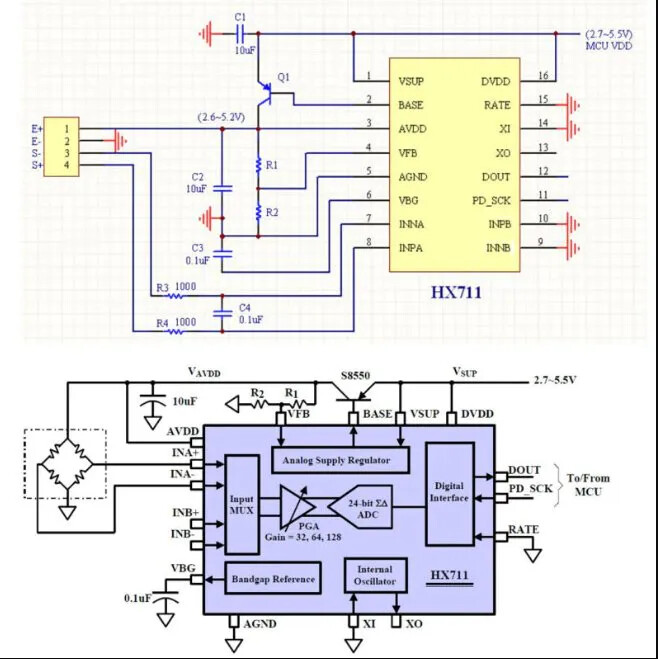
I find this image of a circuit here
here in this website
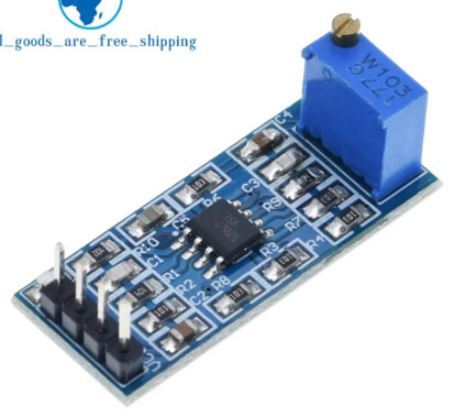
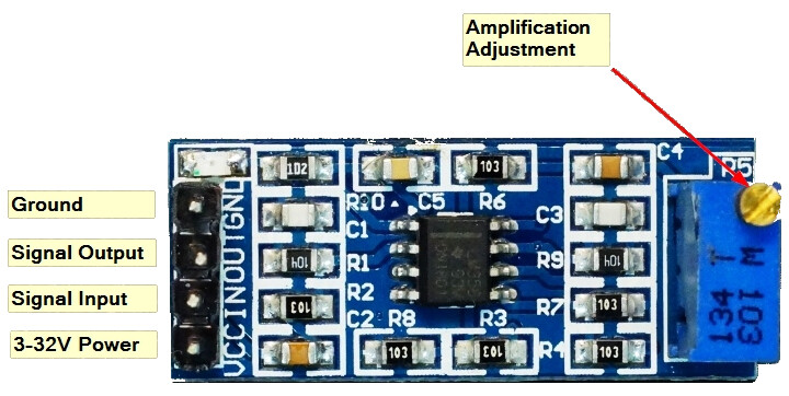
but i have no idea of how to mount this circuit, because my module had only th names VCC, IN, OUT, GND
Oh my God. I don't know about it, I was thinking LM358 works with DC current. I am sorry, it shows how much I donk know about what i am triyng to do.
I already see a little about this possibilitie to change HX711 to 80hz, but I don't have good tools to make this modification here where I am.
Thanks for your ansure.
This is the problem, I don't know how fas I need it be, the aplication is in a dataloggin to take meassures of loads at a car chassis, I think I need something about 100hz or more.
Thanks for your ansure.
Noooooo, oh my God, mabe I can try it. Culd you talk more about it, I only neet to weld this gate and HX711 just change to 80hz? Or I need to do something more?
Thanks for youre ansure.
Post#2, diagram#1.
C2 (left, behind IN) blocks DC.
That, and the large offset and drift of an LM258.
You only need a soldering iron, which is a basic tool in this hobby.
Lift pin15 of the chip off the board with a toothpick after melting the solder. Then connect the pin with a short piece of wire to VCC. Google (images) can also show you how.
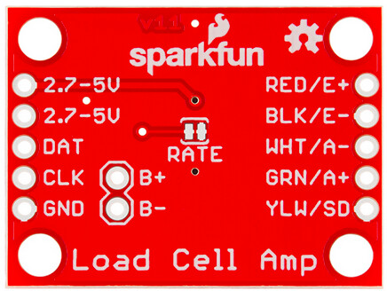
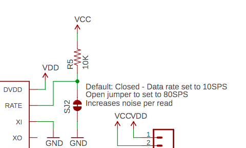
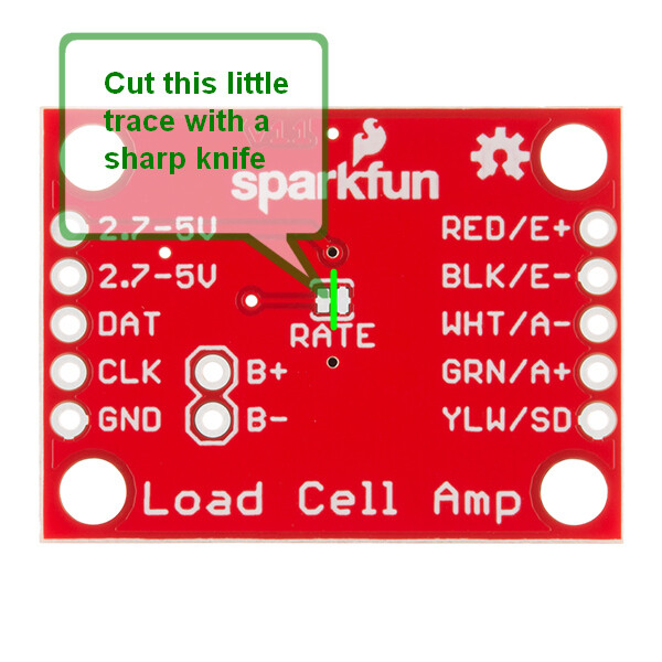
A Sparkfun HX711 board is of course an easier solution. Just cut the tiny trace between the rate fields with a scalpel.
Leo..
I know, but I moved from my city to star a job as an intern, and I broght a soldier iron with me, but in my city the energy is 127V AC and here in this city the energy is 220V AC. So I cant use any tool tha isn't bivolt. But my boad is a copy of sparkfun board, so I think it will be easy just cut something, I will try it.
I realy thank you about your help, mabe it help-me a lot on my andergraduate thesis. If you want to know anithing about Brazil or something like that it would be a pleasure to help you.
Before hacking the board you need to understand what you are doing. Get a copy of the Arduino Cookbook, and then read it. You should also do some tutorials on basic electronics. After this it will be much easier and you will understand what you are doing.
The LM358 is a single supply operational amplifier. It runs from a DC power supply and can work with both AC and DC signals, it is not partial.