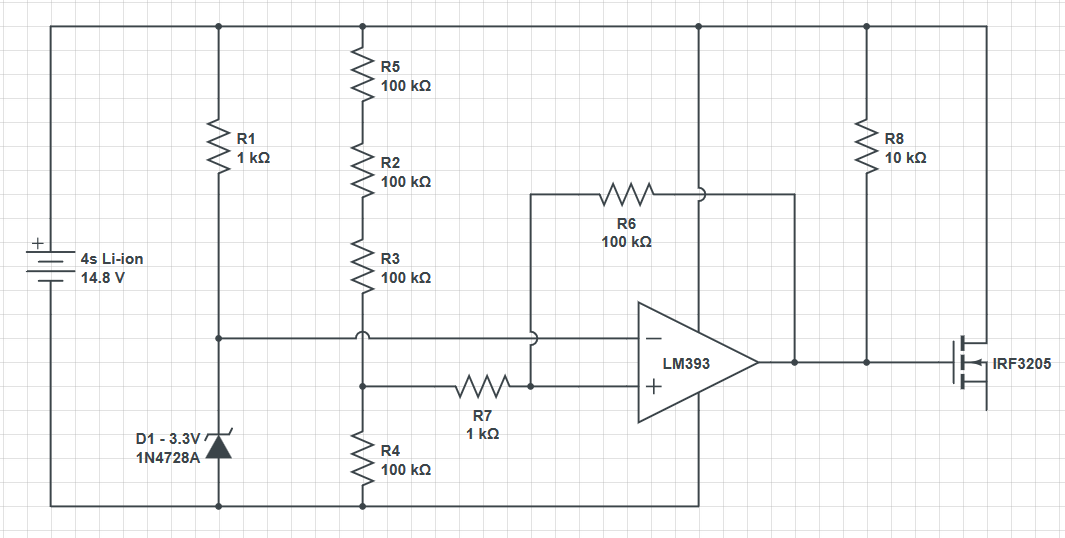
So I needed an over discharge battery protection and I've built something like this:
However something is wrong with this hystereses calculation. The voltage I get to the positive input isn't the total voltage divided by 4.
To add it I used this calculator: http://www.daycounter.com/Calculators/Comparator-Hystereses-Calculator.phtml
Someone can help me please?
What do you mean by "the voltage at the positive input" (where is it measured), and what do you get?
There are two switching points in that circuit, 3.33V and 3.19V (13.3V and 12.8V at the battery terminal).
For high side switching, you should use a P-channel MOSFET.
Consider buying a battery protection circuit, which is cheap and will protect from overcharge, overcurrent and overdischarge.
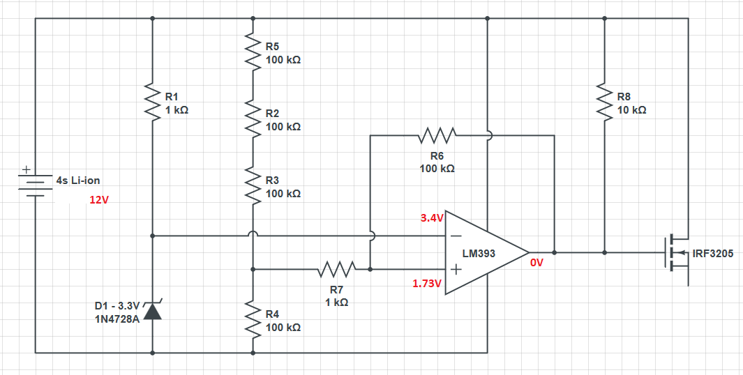
For example when I apply 12V, and I measure the voltage at pin 2 (the minus of the LM393) I get 3.4V which is good. But when I measure the voltage at pin 3 (the plus input) I get 1.73V.
I measure all voltages with respect to ground.
The output voltage(pin 1) is close to zero which is good.
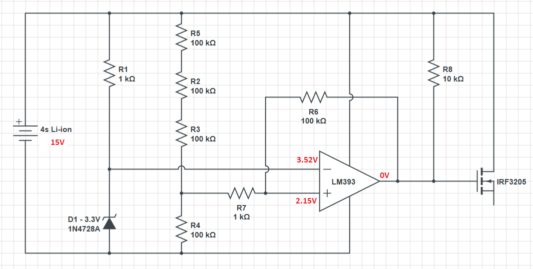
Another try: When I set VCC to 15V, pin 2 voltage is 3.52V, pin 3 is 2.15V, pin 1 is zero.
Are the calculations even correct? Need help
You are not making any sense to me.
My god... Time for pictures I guess:
Now, what should I do to solve this?
Everything is working as should! When the output is 0, your voltage divider is 300k on top and 50k on bottom, with 12V should give 1,714 Volt, very close to what you are reading.
Ciao, Ale.
How did you calculate that? I want it to trip at 13.3V and 12.8V.
Change the zener voltage (es. 5V) and use a multiturn trimmer on the negative input, so you can calibrate your trip point.
Ciao, Ale.
It's just that the hysteresis calculation isn't good. Without R6 and R7, it would work as intended. But it won't have the hysteresis. If I'll put a buffer amplifier, it should also solve the problem. However, isn't there a simpler solution? Can I latch the LM393 to make it stay "0"?
Jabberwock:
How did you calculate that?
Neglecting R7 because it is only 1% of the value of R6, Resistors R6 and R7 are effectively in parallel (both are 'grounded' at one end, and connected together at the other end). Thus they are equivalent to the 50kΩ mentioned by ilguargua. The resistors R2, R3 and R5 add up to 300kΩ.
They form a potential divider with resistors of 300kΩ and 50kΩ.
The output voltage will be the input voltage multiplied by 50/(50 + 300) = 1/7
12V/7 = 1.7V
So I understood that if the ratio of the resistors is high, up tp 100, the change on resistance of the divide resistors will be negligible and also the hysteresis will be small.
So I've changed the circuit a bit. Here is the new one:
However I have two problems, the fist is that the diode zener isn't really accurate, I'm not sure why it's like that. The second one is if it's even possible to determine the potentiometer's value in order to have 3.44V on R4 if VCC is 12.8V. That way the low threshold will be set to what I need it to be.
The voltage on the Zener diode is very likely to be within manufacturer's specified tolerance.
The suggested diode defeats the purpose of the hysteresis circuit.
If you want to experiment with the design, download and learn to use the free LTSpice circuit simulator. It is very accurate for such simple circuits and there are plenty of on line tutorials.
Hi,
Place a 2K potentiometer between R3 and R4, connect the non inverting input to the pot wiper.
Then ADJUST and CALIBRATE your circuit.
Tom... 
PS PLEASE put pin numbers on your circuit, you refer to pins 1,2, 3, but not marked on your schematic.