(note that i changed the pins to DOUT = 2 , SLK = 3)
i have checked the connectivity between dout,slk,vcc and gnd to the arduino board.
i have also checked the resistance between A- & A+ (around 990ohms) and E- & E+ (around 900ohms)
Better to check the voltages.
Hold negative lead of the DMM on the metal shield of the USB socket (ground).
E+ should be close to 4.25volt
E- should be 0.00volt >> important, the board could have a production fault is this is wrong.
A+ and A- should be half of E+
Now measure differential voltage between A+ and A-
It should be <40mV.
Leo..
@laughana
The following sketch will do functional check of the Lod Cells. 1. Connect DT-pin of HX711 Module with A1-pin of UNO. 2. Connect SCK-pin of HX711 Module with A0-pin of UNO. 3. Upload the following sketch.
/* This program takes 10 samples from LC + HX711B at
1-sec interval and then computes the average.
*/
unsigned long x = 0, y = 0;
unsigned long dataArray[10];
int j = 0;
void setup()
{
Serial.begin(9600);
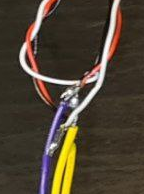
pinMode(A1, INPUT); //DT line //Yellow cable in my Setup
pinMode(A0, OUTPUT); //SCK line //Orange cable in my Set up
}
void loop()
{
for (int j = 0; j < 10; j++)
{
digitalWrite(A0, LOW);//SCK is made LL
while (digitalRead(A1) != LOW) //wait until Data Line goes LOW
;
{
for (int i = 0; i < 24; i++) //read 24-bit data from HX711
{
clk(); //generate CLK pulse to get MSB-it at A1-pin
bitWrite(x, 0, digitalRead(A1));
x = x << 1;
}
clk(); //25th pulse
Serial.println(x, HEX);
y = x;
x = 0;
delay(1000);
}
dataArray[j] = y;
}
Serial.println("===averaging process=========");
unsigned long C1 = 0; //C1 = Count-1 against no fuel in the Tank
for (j = 0; j < 10; j++)
{
C1 += dataArray[j];
}
Serial.print("Average Count = ");
C1 = C1 / 10;
Serial.println(C1, HEX);
}
void clk()
{
digitalWrite(A0, HIGH);
delayMicroseconds(50);
digitalWrite(A0, LOW);
}
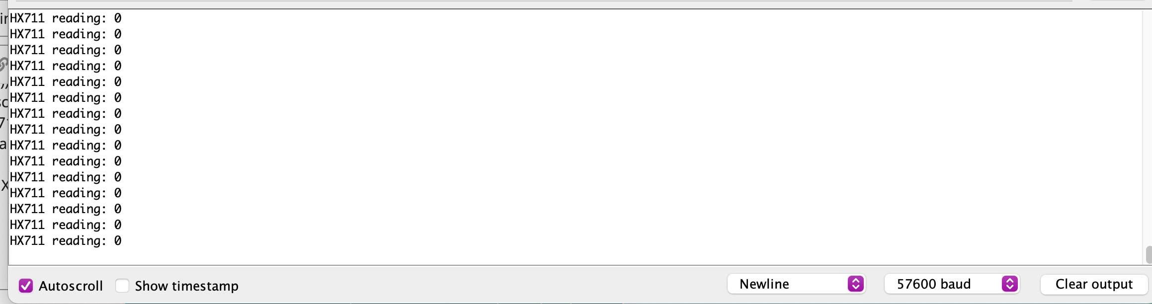
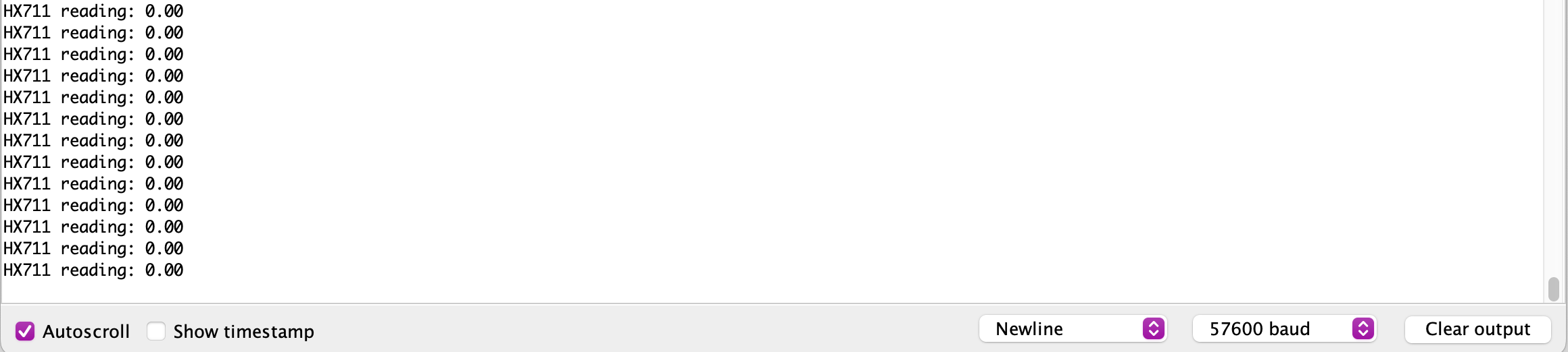
4. Open SM at Bd = 9600. 5. Check that SM shows some counts. 6. Put some weight on the Load Cells; check the count on SM changes.
Hi,
Can you post some images of your project please?
So we can see your layout.
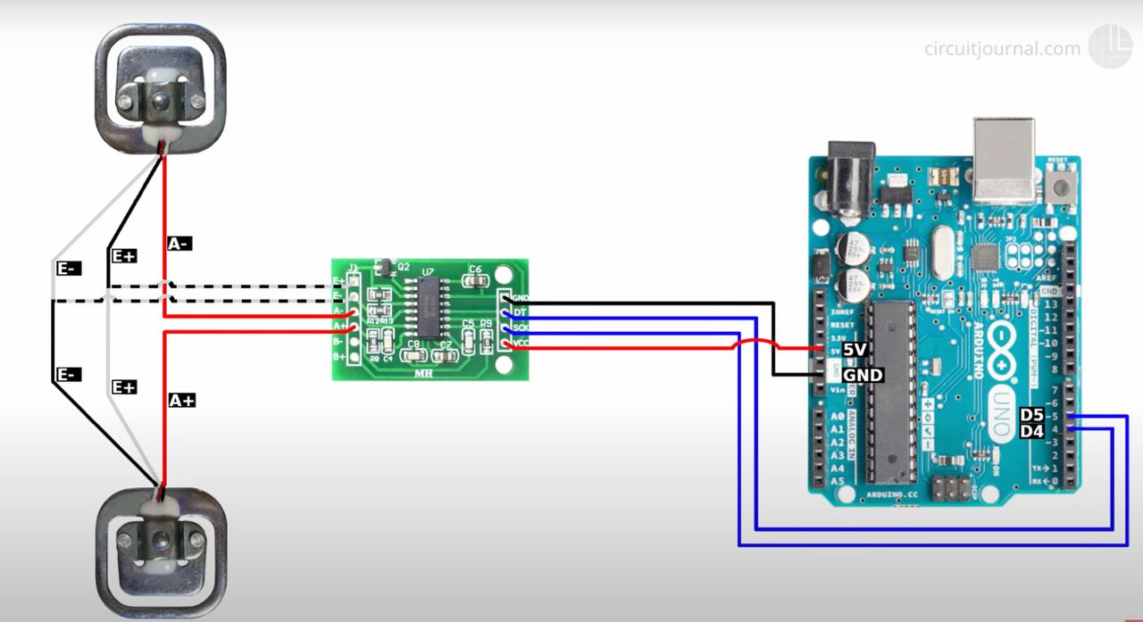
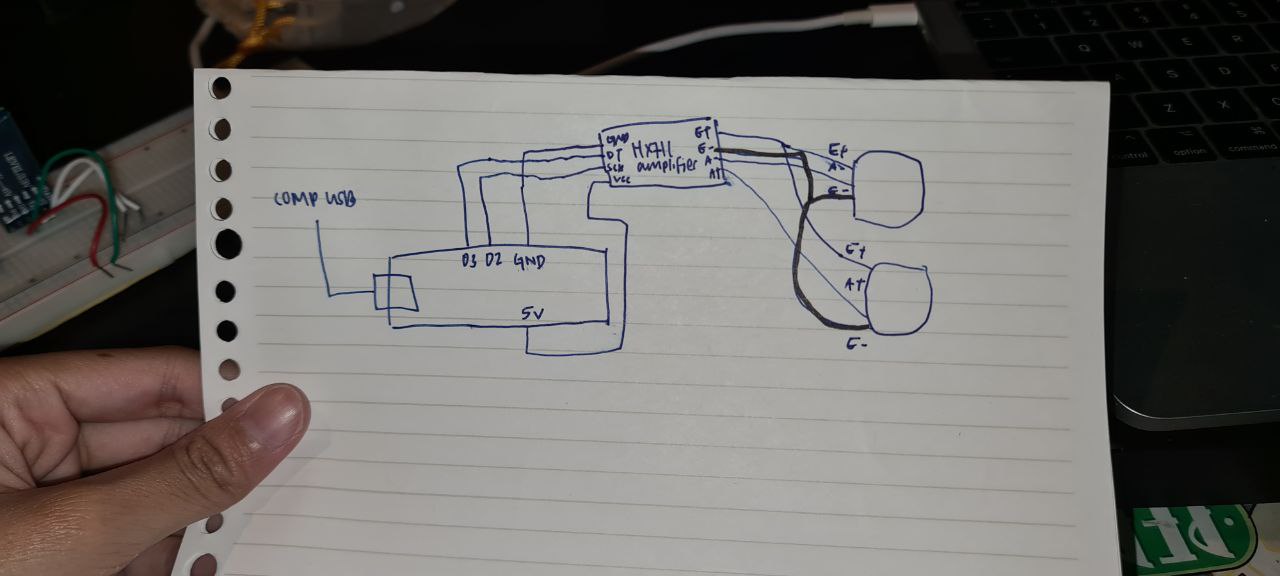
Can we please have a circuit diagram of your project?
An image of a hand drawn schematic will be fine, include ALL power supplies, component names and pin labels.
Now, you have to follow these trouble shooting steps: 1. Connect resistor network with HX711 Module and then connect the module with UNO/NANO as per Fig-1 using short jumpers. Do not connect the LCD.
2. Upload the sketch of post #5. 3. Slowly vary the R3-pot and check that you get changing values on the Serial Monitor. 4. Now remove the resistor network and connect only one load cell with the HX711 Module using short jumpers. 5. Put some varying weight on the load cell and check that the readings on SM changes.
Your jumpers are still too... long. Use single jumper for each connection. Remove the load cell connections completely. You cannot trust the bread board. Some of them are very bad. If have soldering iron, then solder edge connector on the HX711 Module and then use jumpers after continuity check.
Try one more time and then change the HX711 Module if you have a redundant one.
And when you go back to your load cells, put some heat shrink tubes or electrical tape around the connections so the live parts can't touch each other.