I have 6 LED lights that run on 12v with common ground to all 6 lights. Can I control the light functions individually with Arduino and MOSFET transistors without a manual switch? Seems the micro controller pin at transistor gate works fine to blink but all other functions of the lamp do same blinking since on common ground. I want to isolate the 6 LED's and have the transistors control them by turning on and off as needed but since all on common ground I am having issue figuring out how to do this. Let me know how to overcome this if it is possible.
At the first Transistor, I have the one common Ground wire for all 12v LED's going to first transistor drain, the positive leads for all 6 LED's are connected on the 12v rail, the source pin of the first transistor is connected to the 12v ground rail. Arduino lead from pin 13 is connected to the gate of first transistor. I wanted to control the first LED like this and then do same set up individually for the other 5 LED's but seems using different Arduino pins to turn them on and off as needed won't work because everything follows the first transistor....Seems I need a way to isolate so the common ground is isolated between each transistor for each LED to be controlled independently.
BJHenry:
Sure, you'd use PNP transistors (or P channel MOSFET) to switch the 12V supply going to each LED light, instead of switching the common ground.
Yes, I wondered about this. I am using an NPN MOSFET. That makes sense to me to change to a PNP. I might try to draw up a circuit and would welcome any feedback but I get this now. It is basically the reverse of what I tried... Sorry if it seemed like a stupid question....Just learning this hobby.... Thanks!
MTKM:
Yes, I wondered about this. I am using an NPN MOSFET. That makes sense to me to change to a PNP. I might try to draw up a circuit and would welcome any feedback but I get this now. It is basically the reverse of what I tried... Sorry if it seemed like a stupid question....Just learning this hobby.... Thanks!
Don't sweat it at all, we all have to start learning somewhere.
larryd:
Always show a schematic of your circuit, words only, can be difficult to follow.
That is a great schematic, I've never seen it before.
There is no problem controlling as many NPN transistors/ N-MOSFET as you wish. Of course the ground is common that's one of its two other names. The ground is also known as the earth and the common.
larryd:
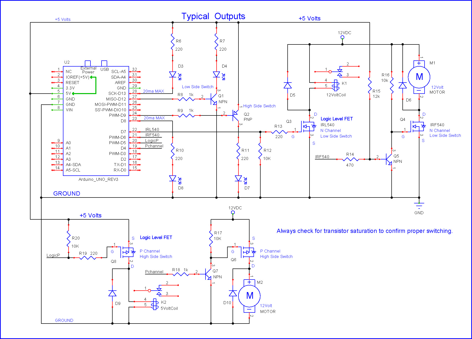
See Q2 and Q8 in the posted schematic as options.
Not if the LED supply is 12volt.
Then you have to use two transistors.
A level shifter and a p-channel mosfet.
The diagram with Q6 and Q7.
I would swap the values of R17 and R18, for faster switching of the mosfet.
D10 can be omitted when driving LEDs.
Leo..
Pull down current of the gate is NPN transistor base current * gain (potentially several hundred mA).
Pull up current of the gate is only about 1mA.
Swapping values evens that out a bit.
Leo..
I found this circuit design. Would this work for controlling the 6 LED functions of the 1 vehicle light I am trying to control with the Arduino if I duplicated the circuit 6 times on a breadboard to show all 6 loads?
I am slightly confused on the need to go through the NPN so explanation on that would be helpful.
Thanks to all !!! I got in the PNP MOSFET's in mail yesterday and set up on breadboard today. Right now I only have 2 functions set up because I need to buy some more 2N3904 transistors. Once those come in I will have all other lights set up and can program the Arduino to do whatever light up sequence needed.