Hello. I am trying to figure out how this Logic Level converter is working.
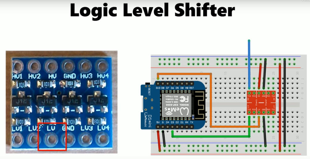
I am trying to connect it like in the picture. Common ground, 5v to the HV pin and 3.3v to the LV pin.
When measuring I have constant 3.3v out on L1 to L4. No matter what I put into H1 to H4.
What am I missing? It says it would be a bidirectional logic level converter.
Please post a hand drawn wiring diagram of your setup, with pins and connections clearly labeled, rather than a misleading, illegible Fritzing showing the wrong part.
1 Like
Well, Since I am trying to figure this out I have used whatever examples I have found. I am using exactly the same things like on the picture.
What is misleading and what is wrong in the picture?
So, I am using a Wemos D1 Mini and the LLC on the left on the picture. And I hooked it up like on the example to the right. Except the green (or blue) wire that I just connect to ground or 3.3v (or 5v) to simulate a 0 or 1.
The low voltage side have constant 3.3v on all L1 to L4.
Am I misunderstanding the function of the LLC?
What are the two devices between which you are putting this level shifter?
A typical interfacing between ESP32 and MEGA is shown below in Fig-1.

Figure-1:
Right now I dont have any devices that are communicating. I just want to verify that I have understood it right, which I apparently haven't. ![]()
I just want to see if I can via this cirquit convert a 3.3v signal to 5v or vice versa.
I am mostly using Arduinos and Wemos D1 but at the end this might be used to communicate between a PLC and a Raspberry Pi.
The HV# pins are pulled-up to 5V and the LV# pins are pulled up to 3V.
With nothing else connected to any of them (assuming proper power connection) you should see, measure, those respective voltages.
When you take one side low (to GND), the corresponding "pin" on the other side should go low, too. If not then something is wrong.
1 Like
Yes there is clearly something wrong if thats how it is supposed to work.
I verified again the status of all L-pins and H-pins. I looks like L1 to L4 is all High. (3.3v).
Oh the H-side there is H1 and H2 that is constantly set to high (5V). H3 and H4 is Low (0v). I can not make any of the pins change state by applying 3.3v och ground on the L-side or 5v or ground to the H-side.
I have tried two different LLCs and they both behave the same way. The Wemos is USB-powered if that would make any difference.
The only change of state that can be effected is by taking a "pin" to GND.
(Feeding in 3V or 5V does not, cannot, change anything.)

See this application note for all the gory details.
As long as you have only connected 3.3V to LV-supply and 5V to HV-supply and you have nothing connected to the LV1 / HV1 Pins you will measure 3.3V / 5V
because the 10K resistors R3 / R4 will pull-up to their voltage

If you really connect a device that is able to pull-down the voltage on the LV1 or the HV1-pin
on the other side the voltage will go down to 0.0V too

The only "dangerous" case without the level-shifter is if you connect a 5V output to an input-pin of a 3.3V-device
In this case the voltage-level-shifter limits the voltage down to 3.3V
or in the opposite case you have a 3.3V output the level-shifter "presents" 5V on the HV1-pin

This means for a real test you could use two 5V devices just to make sure you have no overvoltages one as output (on the HV-side one as input on the LV-side
let the output-pin "blink" once every 5 seconds 5V/0.0V/5V/0.0V and measure the voltage on the LV-side and you will see the voltage on the LV-side will change only between 3.3V/0.0V
best regards Stefan
Hi, @Dernebo
Can you please post some images of your project?
So we can see your component layout.
Thanks.. Tom.. ![]()
![]()
![]()
![]()
https://cdn-shop.adafruit.com/datasheets/an97055.pdf
Bottom of page 10 and top of page 11 explains how this circuit works. Inputs are needed to see how this circuit actions.
Very good explanation. This explanation stays on the functional level which is that level that is needed to understand the basic function of the circuit.
I quote most of the text but added some details to make it easier to understand:
2.3.1 Description of the level shift operation.
For the level shift operation three states has to be considered:
• State 1. No device is pulling down the LV----HV-line.
The bus line of the “Lower voltage” section is pulled up by its pull-up resistors R3 to 3.3 V.
The gate G and the source of the MOS-FET S are both at 3.3 V,
so the voltage between Gate and Source is below the threshold voltage and the MOS-FET is not conducting.
This allows that the bus line at the
“Higher voltage” section is pulled up by its pull-up resistor R4 to 5V.
So the bus lines of both sections are HIGH, but at a different voltage level.
• State 2. A 3.3 V device pulls down the bus line on the LV-side to a LOW level.
The S ource of the MOS-FET becomes also LOW, while the G ate stay at 3.3 V.
The voltage between Gate and Source rises above the threshold and the MOS-FET becomes conducting.
Now the bus line of the “Higher voltage” section is also pulled down to a LOW level by the 3.3
V device via the conducting MOS-FET. So the bus lines of both sections become LOW at the same
voltage level.
• State 3. A 5 V device pulls down the bus line to a LOW level. Via the drain-substrate diode of the MOS-FET the “Lower voltage” section is in first instance pulled down until the voltage between Gate and Source passes the threshold and the
MOS-FET becomes conducting. Now the bus line of the “Lower voltage” section is further pulled down to a LOW level by the 5 V device via the conducting MOS-FET.
So the LV---HV-line of both sections become LOW at the same voltage level.
There is no project to be shown at the moment.
The baseline is:
I have an industrial robot with PLC in/out of 24v. I want to talk to a Raspberry Pi which uses 3.3v in/out. I was looking around in my drawers and found an optocoupler with which I can convert a 5v signal to 24v .
But I need to change the 3.3v to 5v to trigger the optocoupler. Thats when I found the bidirectional LLC and wanted to test it to see if it would work.
I am sorry but I have read and tried to understand a lot of the answers in this thread but my knowledge are a bit limited in this area. ![]() I have been programming Arduinos and other microprocessors as a hobby.
I have been programming Arduinos and other microprocessors as a hobby.
I just wanted to understand how I could use the LLC, but my tests just trying to measure the signals doesnt work at all. II think I might be missing something fundamental here.

This is the initial setup. All L and H inputs/outpots are open and not connected to voltage or GND. The arrowns shows the measurements on all L and H pins without anything connected.
If I pull any of the L or H pins to ground nothing happens on the other side.
Maybe this made it clearer how I have connected everything. What haven't I understood about this?
Your thread is another example why it is a very good idea to post a description- overview of your project and additional writing detail -information of what you want to do.
A voltage-level-converter does not work in your application.
Driving the LED of an optocoupler requires a medium big current 5 mA often 10 mA to 20 mA for reliable operation.
These LLC are build for very low currents to exchange TTL-signals between High-impedance sensors and microcontrollers.
The high-level 5V is realised through a pullup-resistor of 10 kOhm.
This means the current is limited to
5V / 10000 = 0,5 mA. Which is way too less for driving the LED of an optocoupler.
You can use such a TTL-level optocoupler board
best regards Stefan
If you connect a wire from HV1 directly to ground, then you should measure a voltage very close to 0V on LV1.
If not, then check to make sure you have 3.3V and 5V directly on the translator board. If OK then then maybe the pins of the translator board are not making contact in the breadboard.
Just re-check all connections
What you are doing is termed as static test which is not always meaningful. In practice, the level shifter will be subjected to changing signals; our focus would be to looking that the shifter behaves well in the dynamic test bench.
For medium high output-currents this levelshifter should work
The datasheet of the chip says maximum continious output-current 50 mA

connect nothing to the HV1 and HV2 is not 0,0V
connect nothing to the HV1 and HV2 is free floating which results in 3.3V on the LV1/LV2 pin
Only in case you have a real conducting connection from HV1/HV2 to ground
the other side the LV1 / LV2 will go down to 0.0V

another thing that might is the case
these long breadboards have an interruption in the middle of the longside rails which need a bridging wire to connect both halfs together

as a general advice: it is good that you are asking in the forum if something does not (yet) work.
I recommend to stay with professional 24V automation-equipment if you do not want to learn the basics of electronics.
If you want to continue with the rasperry pi etc. I strongly recommend that you really learn the basics of electronics
- what is a voltage-drop?
- what is a voltage-divider?
- ohms-law
- how to read datasheets
- inner resistance of circuits
- input/output-impedance of circuits
best regards Stefan