I have ordered some ATMEGA328P chips, 16Mhz crystals, and 22pf caps. I have also ordered a ICSP programmer, and a SparkFun USB to Serial Breakout - FT232RL.
Just making sure I have what is needed to program the chips as Arduino.
Also, do I need the clock components to program? some of the programmers I have seen circuits that don't show any clock components.
travis_farmer:
I have ordered some ATMEGA328P chips, 16Mhz crystals, and 22pf caps. I have also ordered a ICSP programmer, and a SparkFun USB to Serial Breakout - FT232RL.
Just making sure I have what is needed to program the chips as Arduino.
Also, do I need the clock components to program? some of the programmers I have seen circuits that don't show any clock components.
Thanks in advance for any help.
~Travis
If you have a standard UNO board, and an ISP(ICSP) programmer, That is all you need.
Just install your new 328p's into the UNO board.
Connect the USB to supply power.
Connect the ISP programmer to the UNO.
Configure the Arduino environment to use your ISP programmer(tools/programmer).
Then (tools/burn Bootloader).
You now have a 328p with the bootloader installed. If you build a UNO equivalent circuit, you can just plug in your 'new' UNO chip.
travis_farmer:
clarification on weather or not I need the clock components to program. my research says "yes" if it is programmed by serial, "no" if it is programmed by ICSP. again, just confirming what I found is correct.
And that's why you absolutely need to read the links first. A "raw" chip may not require the clock source, but once the bootloader is loaded, it will no matter which way you program it.
travis_farmer:
Just making sure I have what is needed to program the chips as Arduino.
In addition to the parts you have listed, you will want some 0.1uF capacitors. Connect between VCC and GND and between AVCC and GND, those would be for decoupling.
Connect a resistor between RST and VCC, this would be a pull-up resistor. The ATmega328P has a weak internal pull-up, but it may not be adequate for stability in all circumstances, and is good practice. 1K to 15K is OK, and 10K is probably the most common value used.
Also, to upload via the bootloader using the FTDI adapter, you will want to connect a 0.1uF capacitor between the FTDI adapter's DTR pin, and the ATmega328P RST pin. This will provide auto reset for your uploads.
It is common for people to include a reset button, for manual resets, just like the Uno has. Connect that between RST and GND.
These are some of the finer points that are often missed in tutorials such as the Instructable talked about earlier, but are covered in better tutorials such as Mr. Gammon's and Mr. Burnette's.
Once you have used your programmer to burn the Uno bootloader onto the ATmega328P, you will basically have another Uno. So program it and use it like an Uno. If somebody asks you if you have an extra Uno laying around, the answer is Yes. Technically, it is more like a Duemilanove since the Duemilanove uses an FTDI chip for the USB interface, but upgraded to the Uno bootloader. I recommend this further reading/studying to gain more understanding:
Duemilanove, Pro Mini, Sparkfun ProtoSnap Pro Mini, or Nano schematics
ATmega328P datasheet
Play with an online fuse calculator to learn about the fuse settings (including clock fuse settings)
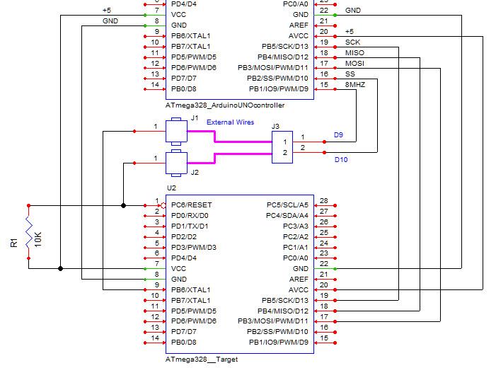
Your Fritzing schematic is very good, and uploading a jpg of the file is a good universal way of sharing even to people who don't have Fritzing installed. I suggest find a tutorial on Eagle. There is a good one on Sparkfun's website. Eagle makes even nicer schematics and Eagle files for the schematic and PCB layout are given on this website, Sparkfun, and other sites for boards such as Uno, Pro Mini, Pro Micro, etc. Eagle is somewhat harder to get started with compared to Fritzing, but you have more parts libraries and flexibility.
For my Atmega328P-PU and Attiny85P-PU projects, I took one of my seldom used UNO's and paired it with a ZIF board from Adafruit. Using the ArduinoISP sketch, this thing just works all the time. The mods were made to be able to use the tiny85 in the area marked by black-marker.
travis_farmer:
thanks, and the Jpeg files are good for smaller schematics, but full size schematics tend to be rather large files.
Downloaded freeware, installed, started it, and was promptly overwhelmed. I shall study some tutorials.
I did run into a lack of parts with Fritzing on occasion, and some of the similar parts aren't quite right.
Thanks again,
~Travis
On most computers you can open a jpeg in a program and re-export it or do a "save as" and there will be a slider or other selection method for choose the quality or compression level. Photos look fairly bad when you choose high compression, but schematics do quite well. You can compress a rather complex jpg schematic to very small. Everybody has a program that will display a jpg, but not everybody has Eagle or Fritzing.