Hey,
I have an DS3231 and I want to turn on an Arduino every day. Alarm on the DS is pretty simple and works. But the SQW Output goes to LOW when Alarm is active.
I want to build a switch which turns on everything when the Alarm starts and uses as less as power as possible when turned of. My Project is drawing 2A Power, so this should also be considered.
Should I use an Relay, Transistor, P-Mosfet, Opto.... and which one and with which scematic... Sorry i am a bit lost in this Transistor and Co kind of stuff
You need a high side switch that turns the power to your project on and off. Or a power supply with a control input. If the low level alarm has the opposite effect you use another transistor to flip the signal.
If all systems are running on the same 5V power supply, It looks like it can be done with one logic level PchFET and two resistors (gate pull-up and damping).
The INT pin of the DS3231 is an active-low open drain output, but the bit weak low-side drive performance.
But I think that's enough to operate the gate of the MOSFET.
In this case, the Arduino will lost power when the DS3231 alarm is cleared.
Thanks a lot @chrisknightley and @WattsThat, this is what i was searching for!
Forgot to mention that I use a LiPo for powering, but this should also work I assume.
How is the DS3231 being powered? It will use a lot less power running on its Vbat input (about 1.5uA) than on its Vcc input (about 100uA). And are you using a DS3231 module that has pullup resistors installed? If so, you may need to disconnect the INT/SQW pin from its pullup resistor.
Thought about powering it from an Pin from the Arduino when it's turned on and when off, running from the Cell battery (so VBat).
And yes, using a module.
I red about removing the pullup, but can someone explain me why, is there a difference between a pullup like in the schematics above and the pullup on the module ?
If it's the ZS-042 module, its pullup resistors pull up to the module's Vcc. So when you power down the Vcc pin, they become pulldown resistors, which means the INT/SQW pin would always be low.
The solution is to cut the trace to the INT's pullup on the module, and make the Arduino interrupt pin INPUT_PULLUP, which provides the replacement pullup.
Really, the only reason you need to power up the RTC via its Vcc is to enable I2C so you can talk to it. The module also has pullups on SDA and SCL, which also pull up to Vcc, so Vcc must be powered up for I2C activity.
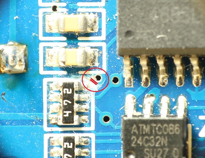
Here's a picture showing the trace to cut if it's the ZS-042 module.
But I see the module has some "problems" (the link is really detailed) and because I am building my own PCB, isn't it smart to integrate the ds3231 directly without the module.
Or is this to complicated? I will have to search for a schematics for that.
It's pretty simple to include it on your PCB. The only reason I can think of why you might not want to do that is if you wanted to be able to replace the whole RTC circuit for some reason. But I don't know why you would need to do that. Just make sure you've figured out the battery holder. Also, you may find that the module is actually cheaper than buying the parts.