Hello,
I am trying to make an interactive 'artwork' as an assignment for university. I want to make something very similar to the magic 8 ball project, but changing the tilt sensor for a push button to change the response on the LCD. could someone tell me how I can change the code so that the button changes the display, and also so that the responses are not randomised but go in order 0,1,2,3...etc. I imagine this is a pretty simple change but Ive never used an Arduino before so have no idea what I'm doing!! However I have just managed to make the Magic 8 ball successfully... so it's all wired up ready to go, I just need to swap the sensor for the button, and change the code. Im working in Mac OS Sonoma 14.6, in Arduino IDE 2.3.4 if that's useful to know. The code I'm using for the Magic 8 ball is below (same as in starter pack project book). Any help would be greatly appreciated!! Thanks
#include <LiquidCrystal.h>
LiquidCrystal lcd(12, 11, 5, 4, 3, 2);
const int switchPin = 6;
int switchState = 0;
int prevSwitchState = 0;
int reply;
void setup() {
  lcd.begin(16, 2);
  pinMode(switchPin, INPUT);
  lcd.print("Ask the");
  lcd.setCursor(0, 1);
  lcd.print("Crystal Ball!");
}
void loop(){
  switchState = digitalRead(switchPin);
  if (switchState != prevSwitchState) {
    if (switchState == LOW) {
      reply = random(8);
      lcd.clear();
      lcd.setCursor(0, 0);
      lcd.print("The ball says");
      lcd.setCursor(0, 1);
      switch(reply) {
        case 0:
        lcd.print("Yes");
        break;
        case 1:
        lcd.print("Most likely");
        break;
        case 2:
        lcd.print("Certainly");
        break;
        case 3:
        lcd.print("Outlook good");
        break;
        case 4:
        lcd.print("Unsure");
        break;
        case 5:
        lcd.print("Ask again");
        break;
        case 6:
        lcd.print("Doubtful");
        break;
        case 7:
        lcd.print("No");
        break;
      }
    }
  }
  prevSwitchState = switchState;
}
pinMode(switchPin, INPUT_PULLUP); // preferred for ordinary pushbuttons
this will be fine. The pushbutton will read HIGH by default because of pinMode(switchPin, INPUT_PULLUP); // preferred for ordinary pushbuttons
and also protect the pin from a short (you need a resistor with a pushbutton and the builtin pullup resistors accomplish this job in the simplest way possible).
You just need to create a counter variable that replaces reply = random(8);
Generally, a global counter of size up to the number or possibilities will be used. You can use an int, but it's preferred to only use a variable that takes up the minimum memory you need. Thus, in your case, a byte will suffice, giving you a range of 256 possibilities (0-255).
byte replyCounter = 0; // I would use this as a blank in your switch(case) state machine
    if (switchState == LOW) {
      replyCounter += 1;
      // keep it in bounds
     if (replyCounter >= 9) replayCounter = 0;
     else if (replyCounter <= 0) replyCounter = 0; // might as well add this condition too
      lcd.clear();
      lcd.setCursor(0, 0);
      lcd.print("The ball says");
      lcd.setCursor(0, 1);
      switch(replyCounter) {
        case 0:
    // blank
        break;
        case 1:
       lcd.print("Yes");
        break;
        case 2:
       lcd.print("Most likely");
        break;
        case 3:
       lcd.print("Certainly");
        break;
        case 4:
       lcd.print("Outlook good");
        break;
        case 5:
        lcd.print("Unsure");
        break;
        case 6:
        lcd.print("Ask again");
        break;
        case 7:
        lcd.print("Doubtful");
        break;
       case 8:
       lcd.print("No");
       break;
       default:
       break;
      }
    }
Amazing!! Thank you. I uploaded it but unfortunately am receiving this error message:
/private/var/folders/th/t4tyzf4n37z80yf92yqb8p0c0000gn/T/.arduinoIDE-unsaved2024118-3254-t9bx6b.0mqx9/sketch_dec8a/sketch_dec8a.ino: In function 'void loop()':
/private/var/folders/th/t4tyzf4n37z80yf92yqb8p0c0000gn/T/.arduinoIDE-unsaved2024118-3254-t9bx6b.0mqx9/sketch_dec8a/sketch_dec8a.ino:18:7: error: 'replyCounter' was not declared in this scope
       replyCounter += 1;
       ^~~~~~~~~~~~
/private/var/folders/th/t4tyzf4n37z80yf92yqb8p0c0000gn/T/.arduinoIDE-unsaved2024118-3254-t9bx6b.0mqx9/sketch_dec8a/sketch_dec8a.ino:20:29: error: 'replayCounter' was not declared in this scope
      if (replyCounter >= 9) replayCounter = 0;
                             ^~~~~~~~~~~~~

exit status 1

Compilation error: 'replyCounter' was not declared in this scope
Hello again,
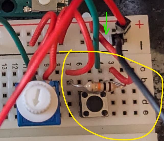
I think I worked out those bits^. The code uploaded fine, but the button doesn't change the screen. I guess I have it in the wrong place on the breadboard perhaps? It positioned at 4c, 4e, 6c, 6e. The lead is going from 4 on the Bboard to the 6 digital pin. I have a resistor at 4b, 7b. I can try sending a pic is that's better.
p.s apologies for my incompetence, again, I have no idea what I'm doing.
#include <LiquidCrystal.h>
LiquidCrystal lcd(12, 11, 5, 4, 3, 2);
const int switchPin = 6;
int switchState = 0;
int prevSwitchState = 0;
int reply;
void setup() {
  lcd.begin(16, 2);
  pinMode(switchPin, INPUT_PULLUP);
  lcd.print("Ask the");
  lcd.setCursor(0, 1);
  lcd.print("Crystal Ball!");
}
void loop(){
  switchState = digitalRead(switchPin);
  byte replyCounter = 0; // I would use this as a blank in your switch(case) state machine
  if (switchState != prevSwitchState) {
    if (switchState == LOW) {
      replyCounter += 1;
      // keep it in bounds
     if (replyCounter >= 9) replyCounter = 0;
     else if (replyCounter <= 0) replyCounter = 0; // might as well add this condition too
      lcd.clear();
      lcd.setCursor(0, 0);
      lcd.print("The ball says");
      lcd.setCursor(0, 1);
      switch(replyCounter) {
        case 0:
    // blank
        break;
        case 1:
       lcd.print("Yes");
        break;
        case 2:
       lcd.print("Most likely");
        break;
        case 3:
       lcd.print("Certainly");
        break;
        case 4:
       lcd.print("Outlook good");
        break;
        case 5:
        lcd.print("Unsure");
        break;
        case 6:
        lcd.print("Ask again");
        break;
        case 7:
        lcd.print("Doubtful");
        break;
       case 8:
       lcd.print("No");
       break;
       default:
       break;
      }
    }
  }
  prevSwitchState = switchState;
}
Use Serial to see if it's the lcd or the sketch. Try this version
#include <LiquidCrystal.h>
LiquidCrystal lcd(12, 11, 5, 4, 3, 2);
const int switchPin = 6;
int switchState = 0;
int prevSwitchState = 0;
// int reply;  // no longer needed
byte replyCounter = 0;  // I would use this as a blank in your switch(case) state machine
void setup() {
  /* open your serial monitor under
    Tools > Serial Monitor at default 9600 baud,
    no line ending */
  Serial.begin(9600);
  lcd.begin(16, 2);
  pinMode(switchPin, INPUT_PULLUP);
  /* notice the (F("some text")); with double brackets
   in the next line?
   That's the F Macro.
   Formatting Serial.print()/Serial.println()
   statements this way causes Serial text to be
   stored in the much larger
   program memory as opposed to the much smaller dynamic memory
   where variables in your sketch live and get changed around.
   In other words, it's preferred to use the F Macro
   for better memory management */
  Serial.println(F("Ask the Crystal Ball!"));
  Serial.println("");  // just a blank line
  lcd.print("Ask the");
  lcd.setCursor(0, 1);
  lcd.print("Crystal Ball!");
}
void loop() {
  switchState = digitalRead(switchPin);
  /* OOPS! This should be declared Globally in your definitions
  byte replyCounter = 0;  // I would use this as a blank in your switch(case) state machine
  */
  if (switchState != prevSwitchState) {
    delay(60);                             // short delay for very crude button debouncing
    switchState = digitalRead(switchPin);  // read it again after the 60mS delay
    if (switchState == LOW) {
      replyCounter += 1;
      // keep it in bounds
      if (replyCounter >= 9) replyCounter = 0;
      else if (replyCounter <= 0) replyCounter = 0;  // might as well add this condition too
      lcd.clear();
      lcd.setCursor(0, 0);
      lcd.print("The ball says");
      lcd.setCursor(0, 1);
      switch (replyCounter) {
        case 0:
          // blank
          break;
        case 1:
          /* you should convert all the rest of these
       Serial.println(""); so they use the F Macro */
          Serial.println("The ball says yes");
          lcd.print("Yes");
          break;
        case 2:
          Serial.println("The ball says most likely");
          lcd.print("Most likely");
          break;
        case 3:
          Serial.println("The ball says certainly");
          lcd.print("Certainly");
          break;
        case 4:
          Serial.println("The ball says outlook good");
          lcd.print("Outlook good");
          break;
        case 5:
          Serial.println("The ball says unsure");
          lcd.print("Unsure");
          break;
        case 6:
          Serial.println("The ball says ask again");
          lcd.print("Ask again");
          break;
        case 7:
          Serial.println("The ball says doubtful");
          lcd.print("Doubtful");
          break;
        case 8:
          Serial.println("The ball says no");
          lcd.print("No");
          break;
        default:
          break;
      }
    }
    prevSwitchState = switchState;
  }
}
Tested on Uno R3, working as expected, although with no LCD screen used in testing. Read notes throughout
Once you have pin 6 in INPUT_PULLUP mode, the button should connect one leg to GND and the other to pin 6, no need for a resistor. Because of the angle of the photo and all wires being red, I wasn't able to identify wether it's connected to (-) or (+) line.
these buttons can be tricky due to their square form. The safest is to use 2 diagonal legs instead of 2 legs of the same side.