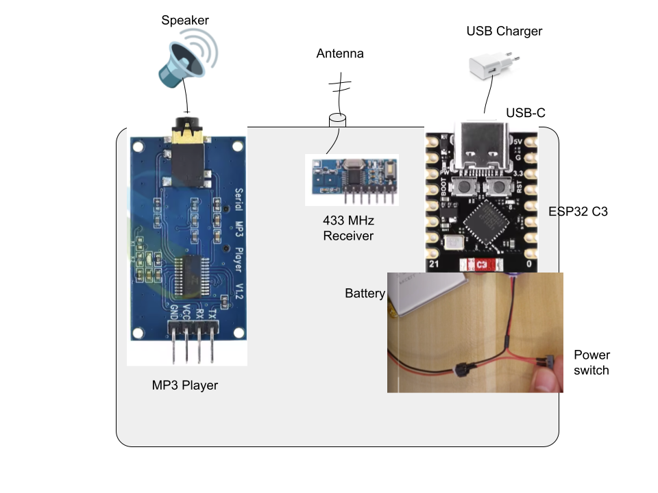
This is a schema of my working product (currently Arduino) - it receives signal from the remote controller and plays the sound. It is my first project so it uses dupont wires to connect it alltogether.
I decided to make it look more professional, 3D print a case for it and design a PCB to make it clean and robust inside.
What I realized is that the receiver and MP3 player are actually PCBs themselves and I'm not sure if I need to create a PCB to plugin these components into it or what do I actually need.
In other words, what shall I do to make the final product clean inside and robust without unnecessary wires where everything is mounted and solid?
For example, the MP3 Player, being a PCB itself, should it be mounted to the "mother PCB" somehow or it should be mounted to the case? Should I use wires to connect it to Arduino/ESP32 or it must be connected using PCB traces in the final product?
You could build a PC board with female headers that the other boards plug into. Put male headers on the ESP32 board so it will also plug in. Then all the wires could be replaced by traces on the PC board. The PC board could also have the battery management circuit.
Soldering everything obviously ensures the most reliable operation. But several of my MP3 player projects have used breadboards to mount the Arduino such as a Nano and a DFR Player module. Care must be taken to firmly secure them, and to keep DuPont wiring short and supported against movement.
Details will obviously depend on each project. Will you want frequent access to update the sketch? To charge a battery, if not using an optional external supply? To add new tracks to the SD card if using one? Etc.
Then I need to solder male headers on each component (ESP32, 433Mhz receiver and the MP3 player) and just plug them in this PCB?
Is the PCB manufacturer able to solder the female headers for me or do I need to do it for each PCB myself?
Is it necessary to secure the male-female connection somehow for the final product or this is considered "safe/robust" as it is?
And regarding the exact design...
The MP3 player has the male pins placed horizontally. Assuming the whole design will be horizontal, I need to "desolder" the male headers and solder them horizontally to plug it in to my PCB horizontally, right?
The last thing I would like to ask to clarify, is how to secure the components to prevent movement.
ESP32 - I assume if I just plug it in to the PCB, it will be solid enough as I'm going to use 10 digital pins.
MP3 player - I assume that just plugging it in is not enough, especially on the side of 3,5mm jack connector it wouldn't be secured at all. The component has 4 mounting holes, so my idea is to print mounting points to my plastic case, create the same 4 mounting holes on the PCB and bolt it together. Assuming that the PCB manufacturer can make the holes. Is this the right approach?
433Mhz receiver - it is a small lightweight component so just plugging it in could be enough?
Thank you and sorry for the trivial questions. I'm a SW guy so I'm discovering the whole new world
Well, since the project is quite simple, I was also considering securing the components from movement as much as possible and simply use short dupont wires. This way I assume it should be "solid enough" but I also want to break into the world of PCBs and make the final product look "almost professional"
Making a PCB is certainly the more professional move. I don't care for dupont wires for finish projects especially single wire jumpers they pull out to easily.
You could design your case so that the main PCB was screwed down and the others are captured by notches when assembled. For instance the MP3 player could have a hole that the speaker jack fit into securing it in place.
I needed something like that recently, initially I thought to use standoffs and glue them to the baseboard, but then I thought since making PCBs is so cheap I would design a PCB. I designed it so that it could use direct pin connections or flying leads. The KK connectors are relatively cheap and resistant to unplugging.
Desoldering headers is tedious without the right tools. Flying leads can probably be secured from working loose with a dab of glue.
You should give it another shot. Few people actually make their own anymore. Just draw it up in software and have it professionally made. Cheap and easy.
Could you please elaborate on how to connect this MP3 Player to the PCB horizontally using direct connection without flying leads? It would be easy if I could place it vertically - would just plug it in to the female headers on the PCB.