-------------------
Thread Summary
-------------------
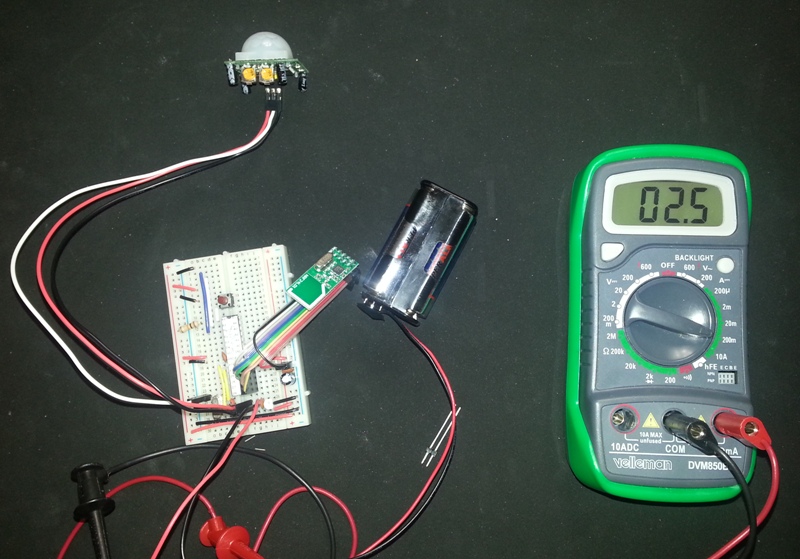
Goal: Make a wireless sensor Arduino run on a few AA batteries for as long as possible. Use RFM69HW wireless module which requires 150mA @ 3.3V. With 3xAA batteries, the Arduino needs to be run between 3.8V to 4.4V. Concerned that when battery starts to run low, 3.8V might be unstable. Sensor will be outside, under an eave, in Ohio whether.
Plan: Use LP3981 voltage regulator for 3.3V. It has a enable pin, so use Arduino output to turn regulator on only when needed. Super low idle current.
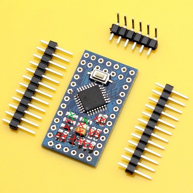
Options 1: Modify an Arduino Pro Mini by removing the voltage regulator components
Advantages: Very small, already comes with the bootloader, super cheap.
Questions: Will it be unstable running the Mini at 16MHz when battery voltage starts to drop below 4V? And the Arduino Mini can actually run ok a less than 5V?
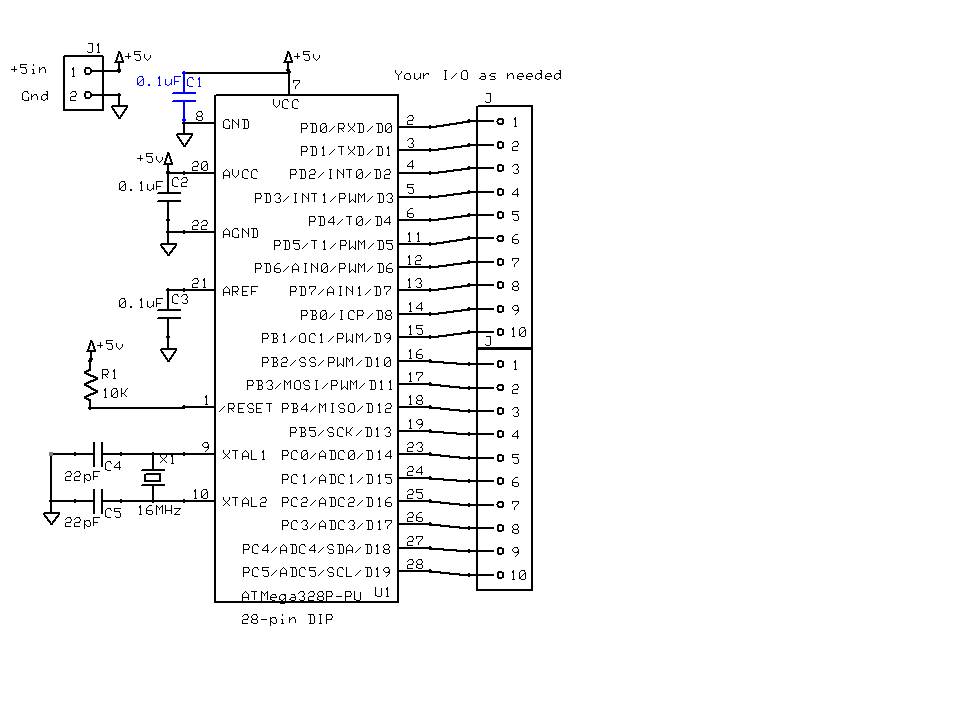
Option 2: Build my own Arduino from parts
Advantages: Able to select an 8MHz osciallator instead of being stuck with 16MHz. Better stability for low voltage application.
Questions: Can the RFM69 (which communicates with Arduino via SPI) still be compatible with an Arduino runnin gat 8MHz?
Original post
Hello,
I'm trying to use a Arduino nano, mini, or lilypad for a battery-powered wireless sensor application. I don't have any of these yet, so I'm looking for guidance.
1) I can't tell from the schematic whether the nano, mini, or the lilypad have LED's built in. I would definitely not want an LED. OK, I can remove these easily.
2) Wireless modules like the RFM69HW or nRF24L01 need 3.3 to 3.9V. If I use three 1.5V AA batteries (preferred battery), I get 4.5V. That's good enough to power the nano, mini, or the lillypad. But how do I get the 3.3V needed to power the wireless module? I don't want to add an external voltage regulator as that would waste way too much power. And I want to sleep the Arduino most of the time. Is the digital output pin 3.3V? Can I power the wireless module from the digital output pin? That would be great because the module could be powered down when the Arduino sleeps. Thanks for the recommendation of using the LP3981 voltage regulator w/ enable pin
3) When the spec on the Arduino that VCC could be 2.5 to 5V, does that mean the digital output voltage also floats with vcc, or does that mean it will regulate the digital output voltage to 3.3, regardless of vcc? Ok, I didn't understand how it works.
4) I've also considered building my own Arduino clone so I can minimize the power draw, not have any LED's. If I stick with three AA batteries, I'll need a 3.3V power regulator for sure. How do I wire it up so that the regulator isn't always sucking power from the Arduino? The power regulator is really just used for the wireless module, since the ATMEGA328 can operate on 4.5V. LP3981 power regulator w/ enable pin.