The maximum current of the DL1 LED is 10 mA. What happens if you set the outputs OUT1, OUT2, OUT3 max current to 40 mA (Current Band Register 03h from the datasheet IS31FL3194)? Will the LED fail?

You need series limiter resistors in line with each LED. The LED's are current mode devices and will conduct until the device output fails, unless limited with a resistor.
You run the danger of letting the "magic smoke" out.
Figure 50 ohms per volt for 20mA. Subtract the LED Vf from the power supply. Say your power is 5V and your led drops 1.6v (typical for a red led), then 5Vps - 1.6Vledfwd = 3.5V × 50 ohms / V = 175 ohms for 20mA.
The maximum current from an Arduino pin is not 40mA. That is the point where the Arduino starts to be damaged.
You can get a lot more current from an Arduino pin if you overload it like you are doing with this circuit. Both the LED and the Arduino will have a short and tortured life.
1 Like
The LEDs are not connected to the pins of the Arduino port, but are connected to the U8 driver chip, which provides a current of 40 mA.
The LED's will draw infinite current without series limiting resistors! Both the Arduino AND the LED's will literally smoke.
The Arduino will not smoke, because inside the U8 driver there is a 10-20-40 mA current limiter. But the LED can smoke. Is this a mistake by the Arduino developers?
You don't understand. The driver is rated for 40mA but YOU HAVE TO PROVIDE CURRENT LIMITING TO THAT VALUE. This is series limiting resistors. Without them, you will put a short across the power supply and the current will increase until one or both parts fails.
Trust us on this or be prepared to buy a new board or U8. Understand that this type of fail can burn traces on your card.
OK my bad, sorry.
Yes it seems like there are restrictions to the maximum current from the driver's data sheet. See this part of the data sheet:-

Normal everyday 5mm LEDs are specified as 20mA normal working, so if you set another level greater that this you will exceed this rating.
It looks like an interesting chip having many modes for generating patterns.
However, you will need some pull up resistors on those I2C lines. And you need to drive them to the correct voltage level, which will depend upon what sort of Arduino you have them connected to.
A full schematic would help.
When LEDs receive too much current then they will dim over time. This can be measured with specialised equipment with over a few days running. But the eye is not good enough to spot the dimming effect and the brain is not good at remembering how bright something was over a few seconds let alone months.
Way, way too much current will fry them almost immediately.
I once ran a red LED at 100mA. It was getting warm. After about an hour, I noticed that it was not glowing bright red as it had been. The power supply indicated that the voltage and current had not changed so the diode was still functioning as it had been. Conclusion: the LED was now emitting infrared light that I could not see instead of the red visible light as before.
Sorry but no. From a solid state physics point of view that is not how LEDs work.
The excess heat and brightness caused a depletion of minority carrier and so there were less of them being excited into the conduction band of the solid state structure.
To shift the light into IR you would have to decrease the energy difference between the conduction band and the valance band. Something you can only do by changing the material the LED is made from.
LEDs only emit light when an electron falls from the conduction band back to the valance band energy. It then emits that energy it has lost in this transition by emitting a photon of light.
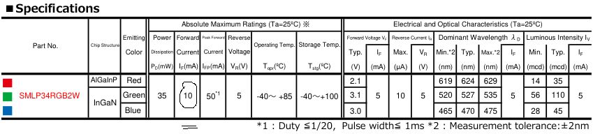
You did not understand me. This is not my schematics, but part of the Arduino Nicla Voice schematics (see below). LED DL1 is tricolor SMD. Its maximum current per R, G, B is 10 mA (see below-below). This is the absolute maximum that the manufacturer prohibits exceeding. Again my question - is this a fault of the schematics developers of Arduino Nicla Voice?
It is a schematic you posted therefore it is your schematic. You are responsible for posting a partial schematic. It is missing pull up resistors on the I2C lines. If there are no pull up resistors in the whole circuit then indeed the people who drew that schematic are in error. However, I would guess that they knew what they were doing.
Finally at post #11 we get to know a lot more about what you are doing. It would have been good to know that at the start.
Oh! So you are saying that the structure of the diode had changed, rather than that a phosphor coating layer had "burned" off.
The topic of this forum thread is "Hardware-Nicla family-Nicla Voice". This means that the questions relate to the schematics of this particular Arduino board [https://docs.arduino.cc/static/521d17d385eae16237b35c3c17c95cd7/ABX00061-schematics.pdf]. Load resistors for I2C are located in the schematics Nicla Voice, there are no questions about them.
You only get a phosphor layer on white LEDs. Basically what I am saying is that the effect of doping semiconductors to get a specific mix of minority carriers has been diminished.
If you do have a white LED and the phosphor burns off then you would get UV light not IR light.
Hey if everybody posted in the correct section I would pay more attention to sections. Until that day I choose to ignore them.
They are not load resistors, they are pull-up resistors. An I2C looks like a floating input when not being used.
So what is your "real" question and has it been answered?
The answer to your original question in post 1 is YES.
He was JOKING!