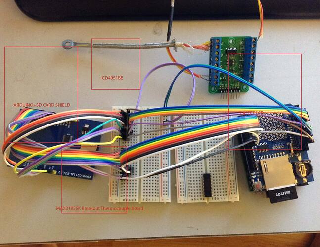
MAX31855K + CD4051BE+ Arduino UNO

Hello,
I am working on Temperature Controller Project.

  1. Arduino UNO

  2. 2.8" TFT LCD
    https://www.amazon.com/Touch-Screen-Socket-Arduino-Module/dp/B00UAA2XIC/ref=sr_1_3?ie=UTF8&qid=1468771525&sr=8-3&keywords=2.8"+tft+lcd+uno

  3. MAX31855K Breakout Thermocouple Board
    http://www.ebay.com/itm/Octo-8-MAX31855-thermocouple-breakout-board-for-5V-systems-type-K-K-type-/251802776832?hash=item3aa09d7500

  4. CD4051BE
    http://www.ebay.com/itm/5-x-CD4051-4051-IC-CMOS-MULTIPLEX-DEMULTIPLEXER-TEXAS-USA-SELLER-Free-Shipping-/231921158288?hash=item35ff940890

  5. SD CARD SHIELD
    https://www.amazon.com/Anycubic-Logging-Shield-Sensor-Arduino/dp/B014PFXKNO/ref=sr_1_2?ie=UTF8&qid=1468771546&sr=8-2&keywords=sd+card+shield

  6. 2 Relays

Current Status:
2.8" TFT LCD is hooked up with Arduino UNO

SD CARD Shield is mounted on Arduino UNO (but code is not currently using it. I will

do this part last.)

On my Arduino UNO:

Pins 2, 3,4,5,6,7 - connected to 2.8"TFT LCD
Analog Pins A0, A1,A2,A3 - Connected to 2.8" TFT LCD

Pins 10,11,12,13 - Vacant (Since I am not using 2.8"TFT LCD SD CARD)
Pins A4, A5 - Vacant

Questions:

  1. Connecting CD4051BE to Arduino UNO : From datasheet, following was the conclusion:

Connect 9 , 10 , 11 pins of CD4051BE to 10,11,12 on Arduino UNO
Connect VCC to VCC and GND to GND
Connect Pin 3 to A4

  1. Connecting MAX31855K Breakout Thermocouple Board

There are 8 pins on MAX31855K Breakout Board: GND T0 T1 T2 +V SO CS SCK

How should I connect MAX31855K to CD4051BE

  1. Coding and Communication : Once I connect MAX31855K to CD4051BE, in my code how should I define the 8 pins (GND T0 T1 T2 +V SO CS SCK)?
    Before when I used to hook up the MAX31855K to Arduino, I just defined 8pins by pin number on Arduino.

  2. Also I need to hook up two relays. After using CD4051BE I have only one digital pin and analog pin left, Pin 13 and A5 respectively.
    I will be able to hook upand connect relay on 2nd CD4051BE?

You provided a lot of information but omitted a schematic. A review of your post reveals you think you should connect the CD4051 power connections to the arduino UNO Vcc (There is NO pin on the arduino UNO labeled Vcc) I know what you meant, but you have to state it explicitly using the given labels on the UNO . This may present a problem . The Max31855 breakout bd has Vin and 3V in. The adafruit site says it is 3.3V to 5V compliant, which seems to imply that the pins are 5V tolerant even though it is a 3.3V device and the only place you can connect 5V to it is the Vin pin (because it's an LDO regulator).
If the CD4051 is running on 5V, it should still accept 3.3V level signals from the 31855 bd. If that doesn't work you can add a CD4050 buffer chip running on 5V and it will do the level translation.

I guess my only question is WHY do you think you need a CD4051 (an analog mux) connected to a breakout board with digital input/outputs ?

That makes no sense at all. Please explain.

Also, I saw no mention of the thermocouple connections .
The 31855 is an 8 TC bd

but STILL is DIGITAL, NOT ANALOG.

SO WHY THE CD4051 ?
That chip is an ANALOG MUX, NOT digital.
What's up ?
What is your electronics background ?
Do you have circuit design experience ?
Have you read any datasheets ?

Hi raschemmel

Sorry about schematic and information I skipped. I will post it as soon as possible. This was my first post and I tried to give as much information as I can, unfortunately I missed some.

And yes, MAX31855K is 8 Thermocouple board.

My initial plan was to use 74HC595 shift out register. So, by connecting MAX31855K to 74HC595 and 74HC595 to Arduino UNO.
But I was not sure if this would have worked.
I should have asked this question first before heading to 4051.

To answer your questions:

"I guess my only question is WHY do you think you need a CD4051 (an analog mux) connected to a breakout board with digital input/outputs ?"

First question I asked myself, Can analog inputs be used as a digital pins?
Reading the below article:

I found yes.

Also , on datasheet: http://www.ti.com.cn/cn/lit/ds/symlink/cd4051b.pdf
They mentioned it can be used for Analog and Digital Multiplexing.

So why can't I provide digital signal to it?

My background is Mechanical Engineering with 1 electronic class in school which I failed twice.

I have never played with IC before. This is the first time I using 74HC595 and CD4051BE.
I could have used Arduino Mega and done with it. But I wanted to learn about multiplexers for a long time now. I know I am going to make mistakes, but it is worth it.

May be CD4051 can be used here. May be you are right. But why it cannot be used?
On the MAX31855K Breakout board, they are using 74HC4051D chip and still supplying digital signal to it. arent they?

If CD4051 would not work,
Would I be able to use 74HC595?

If not, what would you use to get it working? I am out of pins by using tft lcd.

I think you are confused Arduino analog inputs most definitely can be used as digital because the ATmega328 switches between the analog circuit or the digital circuit. The CD4051 is NOT a DUGITAL MUX, PERIOD.

Yes you are absolutely correct! It cannot be used.

Do you think 74HC595 will work though?

I don't know how. Do you have any code for the 31855:?

Yes I do.

Here is the link to it:

Below is the sketch

here is the sketch file:

///////////////////////////////////////////////////////////////////////////////////////////////////////////////////////

/*
MAX31855 library example sketch

This sample code is designed to be used on the MAX31855x8 breakout board.
Look for the MAX31855 breakout boards on www.whizoo.com.

This sample code corresponds to the MAX31855x8 board.  The board has a single MAX31855 IC on it, and uses a multiplexer
to select the correct thermoucouple.  The MAX31855 takes around 100ms to take an accurate temperature reading, so 
the best sample rate one can expect is to sample all 8 channels once-per-second.  If you are only sampling 2 channels
then you can do it 4 times-per-second, and so on.

There are 2 versions of the MAX31855x8 board: 3.3V and 5V.  There is a solder jumper on the board
that can be changed to go from one voltage to the other.

This sample code shows how to take a temperature reading:
1. Set the multiplexer to the correct thermocouple channel
2. Wait 125ms (0.125 seconds) for the MAX31855 to take an accurate reading
3. Get the temperature from the MAX31855 

In the MAX31855 library, there are 2 functions:
1. float readJunction([CELCUIS|FAHRENHEIT])
Returns the internal temperature of the MAX31855 IC

2. float readThermocouple([CELCUIS|FAHRENHEIT])
Returns the temperature of the probe connected to the MAX31855

readJunction() and readThermocouple() will return the temperature, or one of these errors:
#define FAULT_OPEN        10000  // No thermocouple
#define FAULT_SHORT_GND   10001  // Thermocouple short to ground
#define FAULT_SHORT_VCC   10002  // Thermocouple short to VCC
#define NO_MAX31855       10003  // MAX31855 not communicating

Note:  If you connect the thermocouple probe the wrong way around, the temperature will go up
instead of down (and vice versa).  No problem, just reverse the terminals.

Released under WTFPL license.

27 October 2014 by Peter Easton

*/
#include <MAX31855.h>

// Pin connections to the MAX31855x8 board 
// The power requirement for the board is less than 2mA.  Most microcontrollers can source or sink a lot more
// than that one each I/O pin.  For example, the ATmega328 supports up to 20mA.  For convenience, the board
// is placed directly on top of a row of I/O pins on the microcontroller.  Power is supplied to the board by
// holding the GND pin low and the VIN pin high
#define GND  3
#define T0   4
#define T1   5
#define T2   6
#define VIN  7
#define MISO 8
#define CS   9
#define SCK  10

// Create the temperature object, defining the pins used for communication
MAX31855 temp = MAX31855(MISO, CS, SCK);

void setup() {
 // Display temperatures using the serial port
 Serial.begin(9600);
 
 // Initialize pins
 pinMode(GND, OUTPUT);
 pinMode(T0, OUTPUT);
 pinMode(T1, OUTPUT);
 pinMode(T2, OUTPUT);
 pinMode(VIN, OUTPUT);
 
 // Power up the board
 digitalWrite(GND, LOW);
 digitalWrite(VIN, HIGH);
 delay(200);
}


void loop () {
 // Display the junction temperature
 float temperature = temp.readJunction(FAHRENHEIT);
 Serial.print("J=");
 printTemperature(temperature);
   
 // Display the temperatures of the 8 thermocouples
 for (int therm=0; therm<8; therm++) {
   // Select the thermocouple
   digitalWrite(T0, therm & 1? HIGH: LOW);
   digitalWrite(T1, therm & 2? HIGH: LOW);
   digitalWrite(T2, therm & 4? HIGH: LOW);
   // The MAX31855 takes 100ms to sample the thermocouple.
   // Wait a bit longer to be safe.  We'll wait 0.125 seconds
   delay(125);
   
   temperature = temp.readThermocouple(FAHRENHEIT);
   if (temperature == FAULT_OPEN)
       continue;
   Serial.print(" T");
   Serial.print(therm);
   Serial.print("=");
   printTemperature(temperature);
 }
 
 Serial.println();
}


// Print the temperature, or the type of fault
void printTemperature(double temperature) {
 switch ((int) temperature) {
   case FAULT_OPEN:
     Serial.print("FAULT_OPEN");
     break;
   case FAULT_SHORT_GND:
     Serial.print("FAULT_SHORT_GND");
     break;
   case FAULT_SHORT_VCC:
     Serial.print("FAULT_SHORT_VCC");
     break;
   case NO_MAX31855:
     Serial.print("NO_MAX31855");
     break;
   default:
     Serial.print(temperature);
     break;
 }
 Serial.print(" ");
}

/////////////////////////////////////////////////////////////////////////////////////////////////////////////////////////////

OK, I'm confused. HOW can you do a digital read or write to a thermocouple connection ?
That is nothing like the Adafruit MAX31855 breakout bd. That does not compute.
We don't seem to be on the same page.

When I first got the board , I asked myself the same question. But when I tested it, it worked fine. I calibrated the temperatures and it gave correct. Below is cpp file. this may answer your question.

// This library is derived from RocketScream.com's I2C MAX31855 library.
// Please support them from buying products from their web site.
// MAX31855/MAX31855.cpp at master · rocketscream/MAX31855 · GitHub
//
// This is a library for the MAX31855 thermocouple IC
//
// Look for the MAX31855 breakout boards on www.whizoo.com.
//
// Written by Peter Easton (www.whizoo.com)
// Released under WTFPL license
//
// Change History:
// 13 May 2014 Initial Version

#include "MAX31855.h"

MAX31855::MAX31855(int miso, int cs, int clk)
{
_miso = miso;
_cs = cs;
_clk = clk;

// MAX31855 data output pin
// Use internal pullup to be able to detect no connection to the MAX31855
pinMode(_miso, INPUT_PULLUP);
// MAX31855 chip select input pin
pinMode(_cs, OUTPUT);
// MAX31855 clock input pin
pinMode(_clk, OUTPUT);

// Default output pins state
digitalWrite(_cs, HIGH);
digitalWrite(_clk, LOW);
}

/*******************************************************************************

  • Name: readThermocouple
  • Description: Read the thermocouple temperature either in Degree Celsius or
  • Fahrenheit. Internally, the conversion takes place in the
  • background within 100 ms. Values are updated only when the CS
  • line is high.
  • Argument Description
  • ========= ===========
    1. unit Unit of temperature required: CELSIUS or FAHRENHEIT
  • Return Description
  • ========= ===========
  • temperature Temperature of the thermocouple either in Degree Celsius or
  • Fahrenheit. If fault is detected, FAULT_OPEN, FAULT_SHORT_GND or
  • FAULT_SHORT_VCC will be returned. These fault values are outside
  • of the temperature range the MAX31855 is capable of.
    *******************************************************************************/
    double MAX31855::readThermocouple(unit_t unit)
    {
    unsigned long data;
    double temperature;

// Initialize temperature
temperature = 0;

// Shift in 32-bit of data from MAX31855
data = readData();

// Is this a MAX31855? Bits 3 and 17 must be zero
if (data & 0x20008)
return NO_MAX31855;

// If fault is detected
if (data & 0x00010000)
{
// Check for fault type (3 LSB)
switch (data & 0x00000007)
{
// Open circuit
case 0x01:
temperature = FAULT_OPEN;
break;

// Thermocouple short to GND
case 0x02:
temperature = FAULT_SHORT_GND;
break;

// Thermocouple short to VCC
case 0x04:
temperature = FAULT_SHORT_VCC;
break;
}
}
// No fault detected
else
{
// Retrieve thermocouple temperature data and strip redundant data
data = data >> 18;
// Bit-14 is the sign
temperature = (data & 0x00001FFF);

// Check for negative temperature
if (data & 0x00002000)
{
// 2's complement operation
// Invert
data = ~data;
// Ensure operation involves lower 13-bit only
temperature = data & 0x00001FFF;
// Add 1 to obtain the positive number
temperature += 1;
// Make temperature negative
temperature *= -1;
}

// Convert to Degree Celsius
temperature *= 0.25;

// If temperature unit in Fahrenheit is desired
if (unit == FAHRENHEIT)
{
// Convert Degree Celsius to Fahrenheit
temperature = (temperature * 9.0/5.0)+ 32;
}
}
return (temperature);
}

/*******************************************************************************

  • Name: readJunction
  • Description: Read the thermocouple temperature either in Degree Celsius or
  • Fahrenheit. Internally, the conversion takes place in the
  • background within 100 ms. Values are updated only when the CS
  • line is high.
  • Argument Description
  • ========= ===========
    1. unit Unit of temperature required: CELSIUS or FAHRENHEIT
  • Return Description
  • ========= ===========
  • temperature Temperature of the cold junction either in Degree Celsius or
  • Fahrenheit.

*******************************************************************************/
double MAX31855::readJunction(unit_t unit)
{
double temperature;
unsigned long data;

// Shift in 32-bit of data from MAX31855
data = readData();

// Is this a MAX31855? Bits 3 and 17 must be zero
if (data & 0x20008)
return NO_MAX31855;

// Strip fault data bits & reserved bit
data = data >> 4;
// Bit-12 is the sign
temperature = (data & 0x000007FF);

// Check for negative temperature
if (data & 0x00000800)
{
// 2's complement operation
// Invert
data = ~data;
// Ensure operation involves lower 11-bit only
temperature = data & 0x000007FF;
// Add 1 to obtain the positive number
temperature += 1;
// Make temperature negative
temperature *= -1;
}

// Convert to Degree Celsius
temperature *= 0.0625;

// If temperature unit in Fahrenheit is desired
if (unit == FAHRENHEIT)
{
// Convert Degree Celsius to Fahrenheit
temperature = (temperature * 9.0/5.0)+ 32;
}

// Return the temperature
return (temperature);
}

/*******************************************************************************

  • Name: readData
  • Description: Shift in 32-bit of data from MAX31855 chip. Minimum clock pulse
  • width is 100 ns. No delay is required in this case.
  • Argument Description
  • ========= ===========
    1. NIL
  • Return Description
  • ========= ===========
  • data 32-bit of data acquired from the MAX31855 chip.

*******************************************************************************/
unsigned long MAX31855::readData()
{
int bitCount;
unsigned long data;

// Clear data
data = 0;

// Select the MAX31855 chip
digitalWrite(_cs, LOW);

// Shift in 32-bit of data
for (bitCount = 31; bitCount >= 0; bitCount--)
{
digitalWrite(_clk, HIGH);

// If data bit is high
if (digitalRead(_miso))
{
// Need to type cast data type to unsigned long, else compiler will
// truncate to 16-bit
data |= ((unsigned long)1 << bitCount);
}

digitalWrite(_clk, LOW);
}

// Deselect MAX31855 chip
digitalWrite(_cs, HIGH);

return(data);
}
Contact GitHub API Training Shop Blog About
© 2016 GitHub, Inc. Terms Privacy Security Status
Suppose I have defined all output pins on 74HC595.
D0
D1
D2
D3
D4
D5
D6
D7

Wouldn't I be able to define these pins to MAX31855K Octo Thermocouple board pins?

GND - D0
T0 - D1
T1 - D2
T2 - D3
+V - D4

Now as per logic chart printed behind the board:


T2 T1 T0 THERM
L L L 0
L L H 1
L H L 2
L H H 3
H L L 4
H L H 5
H H L 6
H H H 7

Wouldn't I be able to digitalwrite(T2 , High)
digitalwrite(T1, High)
digital write( T0 High) ?

So, That is what I thought.

the other question is where would I connect SCK, CS and CO pins on Breakout board to? I am not sure how would I read temperatures as 595 is sending output signals.

Can I connect SCK, CS, and CO to ICSP header?

What I mean is T0 & T1 are the thermocouple connections , not the arduino connections and thermociuples are not compatible with digital signals.

Post a photo of hand drawn schematic.

That's stupid. Those are ADDRESS lines !
They should be labeled A0,A1 & A2 !
(NOT T0, T1 , & T2 !)

I think you can forget abiut using the 595.
That isn't going to work because the data is a packet, not individual bits. The 595;is a horse in a dog show.
No you CAN'T.

All I know is, Octo Thermocouple MAX31855K Breakout Board has a 74HC4051 and MAX31855K on it.

You can connect 8 k-type thermocouples to this board. and The 8 pins I mentioned before is connected on DigitalI/O pins.

I don't know how T0, T1 T2 are able to take digital signals.

I usually plug to analog inputs. But this was different.

I have attached the picture between ARduino and Octo thermocouple MAX31855K Breakout board .

And I am working on schematic for Arduino, LCD, 74HC595 and Octo thermocouple MAX31855K Breakout board using fritzing. I am half way there.

You said you already tested it so what's the issue ?
(besides the fact you can't use a 595)

There's no mystery about the onboard 4051
but that has nothing to do with you and you should forget that you know that because it is NOT there for you to use. It is the MUX used MUX the voltages to the onboard ADC.

WHY ( on earth) would you connect GND to D0 ?
WHAT ( on earth) is C0 ?

Suppose I have defined all output pins on 74HC595.
D0
D1
D2
D3
D4
D5
D6
D7

Wouldn't I be able to define these pins to MAX31855K Octo Thermocouple board pins?

GND - D0
T0 - D1
T1 - D2
T2 - D3
+V - D4

No. You can't connect the GND to a digital pin.
And you can't connect +V to a digital pin.
I don't know where you are getting these crazy ideas but stop it.

Now as per logic chart printed behind the board:
http://i.ebayimg.com/images/g/yyMAAOSw1vlUwIGW/s-l1600.jpg

T2 T1 T0 THERM
L L L 0
L L H 1
L H L 2
L H H 3
H L L 4
H L H 5
H H L 6
H H H 7

Wouldn't I be able to digitalwrite(T2 , High)
digitalwrite(T1, High)
digital write( T0 High) ?

Yes, if you want to select TC #7.

t

The other question is where would I connect SCK, CS and CO SO pins on Breakout board to?

There is no "C0"
It's "SO". (for Serial Out)

I am not sure how would I read temperatures as 595 is sending output signals.

You can't use the 595.

Can I connect SCK, CS, and CO SO to ICSP header?

Only if your code expects them to be there.

I guess my best option is going with Arduino Mega then.
Thanks for your help raschemmel.

It should be obvious that a SPI interface is digital and not analog so the 4051 couldn't possibly connected to the "outside world". ( with the exceotion of the thermociuples)

I don't see how a Mega would help with serial SPI interface