MAX7219 7 segment display not working

Hello! Newb here trying to get an 8 digit 7 segment MAX7219 display working with Arduino Nano ESP32. I've seen and read other posts here and elsewhere on the internet and I'm not having luck.

I bought these displays from amazon: Amazon.com: AOICRIE 6 PCS 8-Digit 7 Segment MAX7219 Digital Segment Module, Seven Section 8 Bit LED Display Tube for MCU/51/AVR/STM32 for Raspberry Pi ESP8266 Nodemcu (Pack of 6) : Industrial & Scientific

After messing with them, I could get all the segments to light up when plugged in, but couldn't get any actual readout. I'm using the LedControl library, and demo code which I posted below. I've tried different pins, no luck. After reading the reviews for these displays, I figured maybe they were just low quality. May people complaining of issues, not working, stopped working. The MAX7219 chip on the display is blank and reviews are calling it questionable.

So I bought these displays which have better reviews and actually have the part number printed on the chips: Amazon.com: HiLetgo 2pcs MAX7219 8-Digital Segment Digital LED Display Tube for Arduino 51/AVR/STM32 : Industrial & Scientific

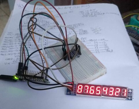
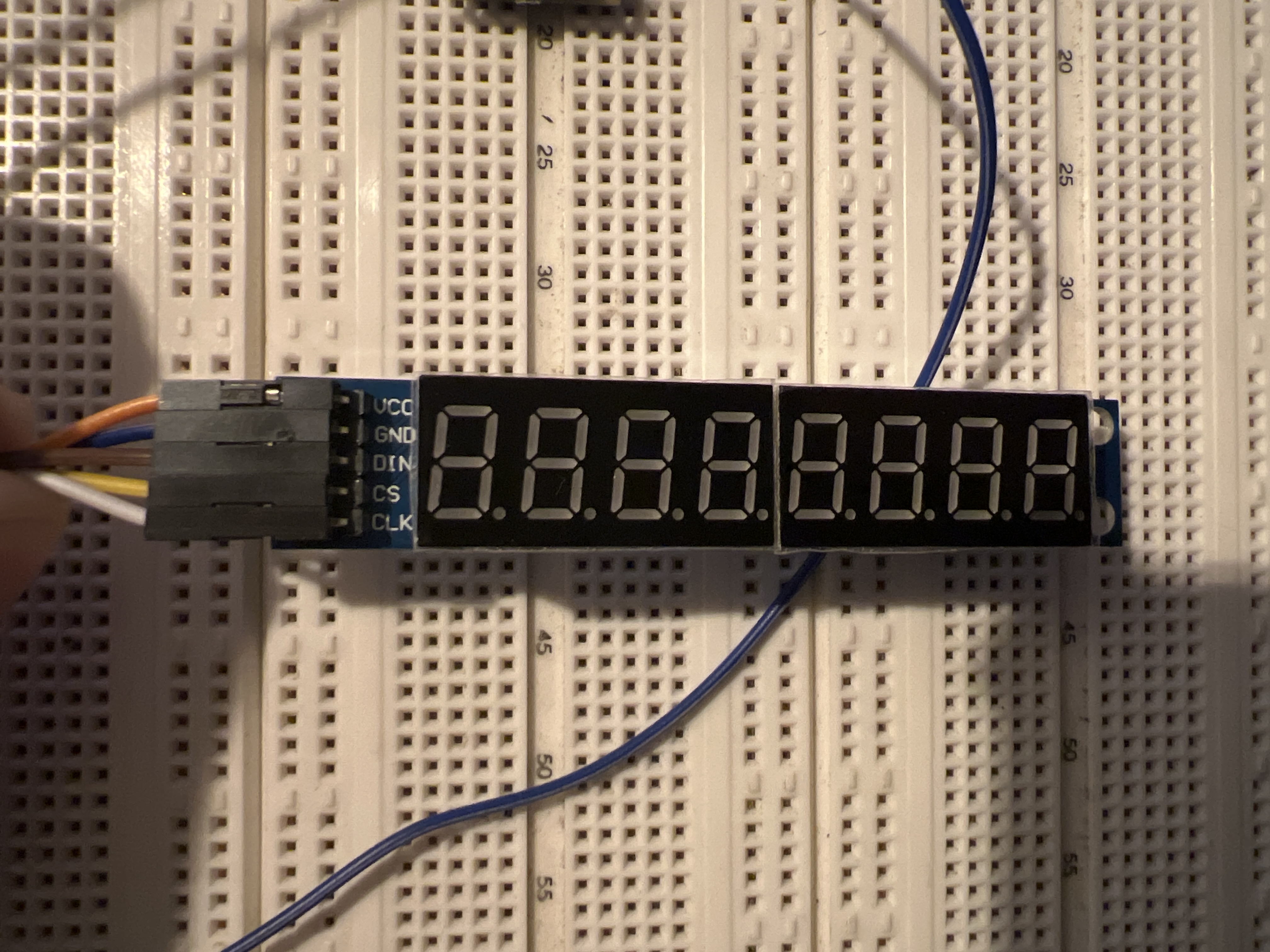
My result were basically the same. The entire display will light up if rebooted, but I can't get any sort of readout.

Other commenters say to check the connections. I've tried using a breadboard and M-F cables. I've tried F-F cables to connect the nano to the display. I've used short cables, longer cables. Nothing seems to make a difference. The nano is new and I've had success using it for other sensors and LEDs so far. But I'm struggling to get anything useful to display on them. So far I have 8 displays, and none are working as expected.

I'm using the pin out in the demo code which is included with the LedControl library, it's unmodified.

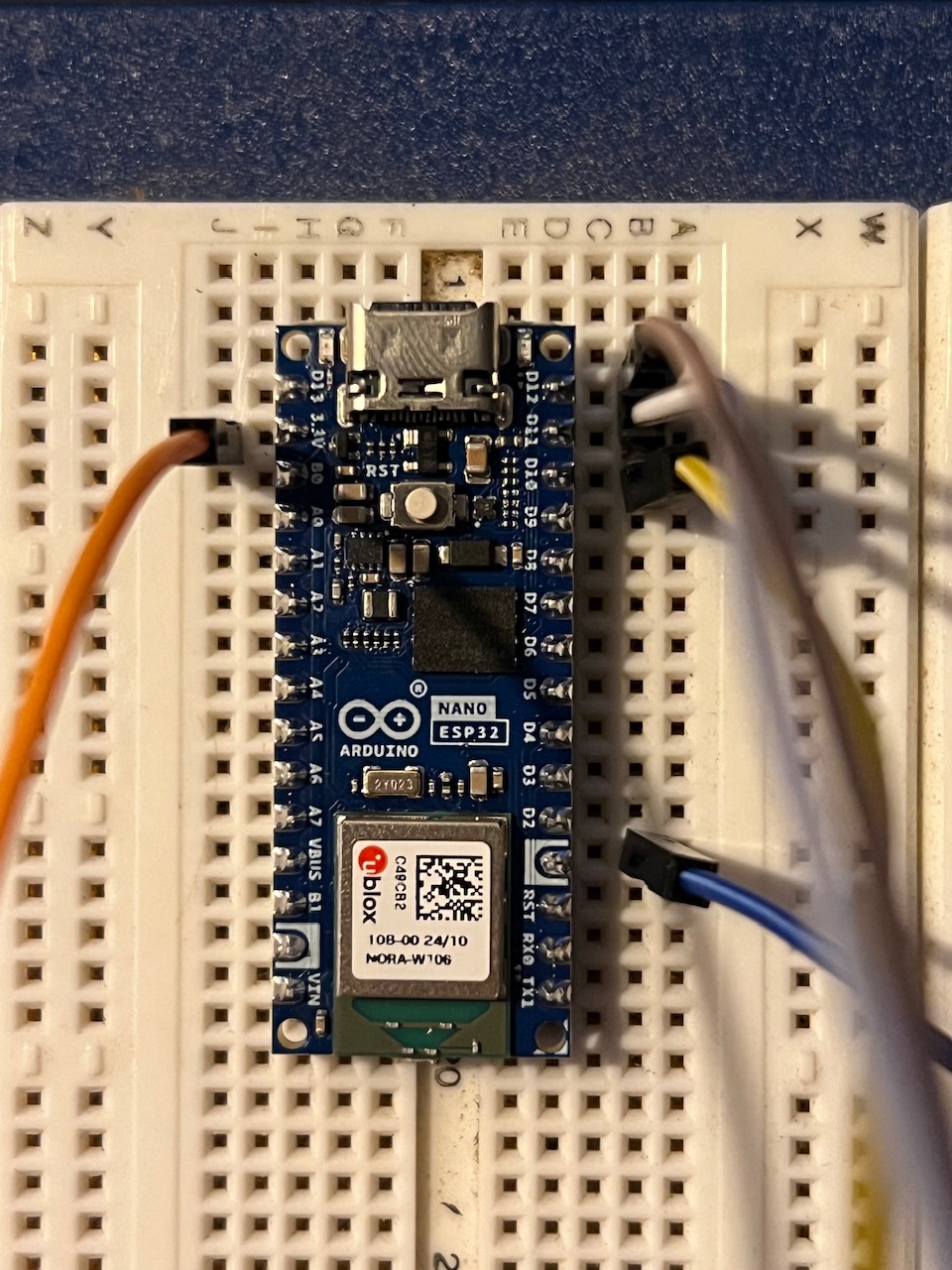
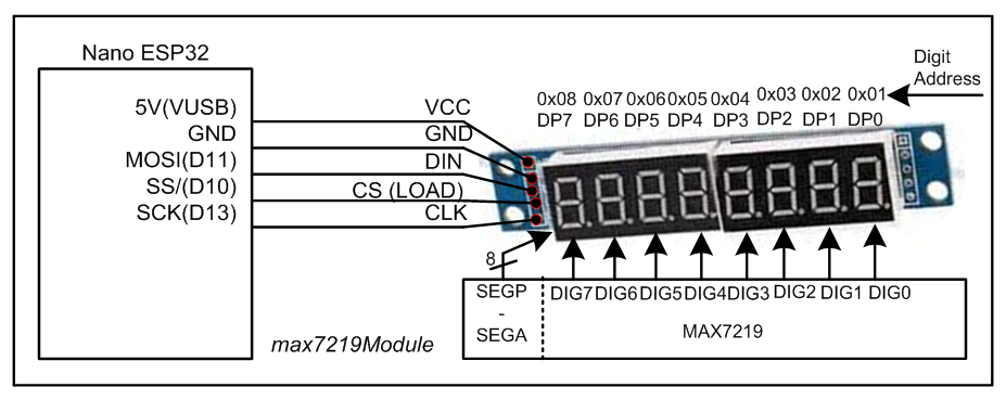
pin 12 is connected to the DataIn <--> DIN on the display
pin 11 is connected to the CLK <--> CLK on the display
pin 10 is connected to LOAD <--> CS on the display

I've tried 5v and 3.3v power from the nano. I tried adding a 500ohm resistor to the datapin shown here:

I'm not sure what else to try at this point. Any tips would be appreciated!


//We always have to include the library
#include "LedControl.h"

/*
 Now we need a LedControl to work with.
 ***** These pin numbers will probably not work with your hardware *****
 pin 12 is connected to the DataIn 
 pin 11 is connected to the CLK 
 pin 10 is connected to LOAD 
 We have only a single MAX72XX.
 */
LedControl lc=LedControl(12,11,10,1);

/* we always wait a bit between updates of the display */
unsigned long delaytime=250;

void setup() {
  /*
   The MAX72XX is in power-saving mode on startup,
   we have to do a wakeup call
   */
  lc.shutdown(0,false);
  /* Set the brightness to a medium values */
  lc.setIntensity(0,8);
  /* and clear the display */
  lc.clearDisplay(0);
}


/*
 This method will display the characters for the
 word "Arduino" one after the other on digit 0. 
 */
void writeArduinoOn7Segment() {
  lc.setChar(0,0,'a',false);
  delay(delaytime);
  lc.setRow(0,0,0x05);
  delay(delaytime);
  lc.setChar(0,0,'d',false);
  delay(delaytime);
  lc.setRow(0,0,0x1c);
  delay(delaytime);
  lc.setRow(0,0,B00010000);
  delay(delaytime);
  lc.setRow(0,0,0x15);
  delay(delaytime);
  lc.setRow(0,0,0x1D);
  delay(delaytime);
  lc.clearDisplay(0);
  delay(delaytime);
} 

/*
  This method will scroll all the hexa-decimal
 numbers and letters on the display. You will need at least
 four 7-Segment digits. otherwise it won't really look that good.
 */
void scrollDigits() {
  for(int i=0;i<13;i++) {
    lc.setDigit(0,3,i,false);
    lc.setDigit(0,2,i+1,false);
    lc.setDigit(0,1,i+2,false);
    lc.setDigit(0,0,i+3,false);
    delay(delaytime);
  }
  lc.clearDisplay(0);
  delay(delaytime);
}

void loop() { 
  writeArduinoOn7Segment();
  scrollDigits();
}

Make a wiring drawing of this.

A quick check of the MAX7219 datasheet reveals that the minimum Vcc is 4.0V. And the minimum Vih is 3.5V. The Nano ESP32 is a 3.3V board, I believe? You're going to need to run the display on 5V and use level shifters between the Nano's outputs and the display's inputs.

I had a member message me stating this too. It does have a 3.3v pin and a 5v pin, I think? I’ll measure the voltages. I also purchased a nano every today to test out.

I really appreciate all the feedback. I’d love to get this to work with the nano esp32 just so I can learn more about it.

Is there a go to tool for this?

My go-to is ASCII, but most opt for online or offline graphic, circuit diagram software... or pen and paper.

                                                   +------------------------+            +------------------------+
           +-------------------------+        +----| 1 -+ ANODE    EMIT|/>3 |------------| DIM+   MEANWELL        |
           | EN    ESP32    MOSI D23 |        |    |    v    PC817X    |    |       +----| ACL     HLG240H        |
           | VP    DEVKIT    SCL D22 |------+ |    |   === OPTOCOUPLER |    |       | +--| ACN                Vo+ |-----+
           | VN              TX0 TX0 |  +---|-|----| 2 -+ CAT     COLL |\-4 |-------|-|--| DIM-               Vo- |---+ |
           | D34                 RX0 |  |   | 2    +------------------------+       | |  +------------------------+   | |
           | D35             SDA D21 |--|-+ | 2    +-------------------------+      | |  +------------------------+   | |
      +----| D32 PWM             D19 |  | | | 0    | WALL POWER          ACL |----+ | |  |    LED lighting        |   | |
      | +--| D33 PWM             D18 |  | | | R    |                     ACN |--+-|-|-+  |                      + |---+ |
      | |  | D25                 D05 |  | | | E    +-------------------------+  | | |    |                      - |-----+
      | |  | D26                 TX2 |  | | | S    +-------------------------+  | | |    +------------------------+
      | |  | D27                 RX2 |  | | | I    | 5V      RELAY       GND |--+ | |
      | |  | D14                 D04 |  | | | S    | GND                 COM |----+ |
      | |  | D12                 D02 |  | | | T +--| DIN                 N.O.|------+
      | |  | D13                 D15 |  | | | O |  +-------------------------+
      | |  | GND                 GND |--+ | | R |  +-------------------------+
      | |  | VIN                 3V3 |--|-|-|-|-|--| VIN              BH1750 |
      | |  +-------------------------+  +-|-|-|-|--| GND              Light  |
      | |                                 | +-|-|--| SCL              Sensor |
      | |                                 +---|-|--| SDA                     |
      | +-------------------------------------+ |  | ADDR                    |
      +-----------------------------------------+  +-------------------------+

Try the following sketch with a level shifter to see 87654321 on the display unit.
D10 ----> CS (LOAD)
D11 ----> DIN (MOSI)
D12 ----> no connection
D13 -----> SCK

#include<SPI.h>
byte registerAddress[] = {0x0C, 0x09, 0x0A, 0x0B}; //control registers of MAX7219, see data sheets
byte registerData[] = {0x01, 0x00, 0x01, 0x07}; //[1] = brightness = min, FF = max
//normal modeo; no-decode;intensity;8-digit scan
byte dataArray[8];  //to hold cc-codes (no-decode format)
byte digitAddress[] = {0x01, 0x02, 0x03, 0x04, 0x05, 0x06, 0x07, 0x08};//DP0-DP7
byte lupTable[] = {0x7E, 0x30, 0x6D, 0x79, 0x33, 0x5B, 0x5F, 0x70,
                   0x7F, 0x7B, 0x77, 0x1F, 0x4E, 0x3D, 0x4F, 0x47
                  }; //0, 1, ...., E, F ; no-decode cc-code see data sheets

void setup()
{
  pinMode(10, OUTPUT);  //LOAD Pin of MAX7219
  //-------------------
  SPI.begin();
  // bitSet(SPCR, 4);              //UNO is Master SPI
  //  SPI.setBitOrder(MSBFIRST);    //MSB_bit will be transferred first
  //SPI.setClockDivider(SPI_CLOCK_DIV128); //TX rate = 16MHz/128 = 125 kbit
  //  SPI.setDataMode(SPI_MODE1);//MOSI is sampled at the rising edge of CLK
  //------------------------------------------------
  digitalWrite(10, LOW);      //Low at LOAD pin
  //---- dataArray update-----------------------------
  dataArray[0] = lupTable[1];   //no-decode cc-code of digit-4
  dataArray[1] = lupTable[2];   //n0-decode cc-code of digit-5
  dataArray[2] = lupTable[3];   //no-decode cc-code of digit-6
  dataArray[3] = lupTable[4];   //no-decode cc-code of digit-7
  dataArray[4] = lupTable[5];   //no-decode cc-code of digit-4
  dataArray[5] = lupTable[6];   //n0-decode cc-code of digit-5
  dataArray[6] = lupTable[7];   //no-decode cc-code of digit-6
  dataArray[7] = lupTable[8];   //no-decode cc-code of digit-7
  //-------------------------------------------------


  //---keep intializing the Mode of Operation------------
  for (int i = 0; i < 4; i++)
  {
    SPI.transfer(registerAddress[i]);
    SPI.transfer(registerData[i]);
    digitalWrite(10, LOW);
    digitalWrite(10, HIGH); //assert LH/LL on LOAD pin
    digitalWrite(10, LOW);
  }

  //--keep transferring the result/data----------------------
  for (int i = 0; i < 8; i++)
  {
    SPI.transfer(digitAddress[i]); //DPX position
    SPI.transfer(dataArray[i]);   //shows 4 5 6 7 on display
    digitalWrite(10, LOW);
    digitalWrite(10, HIGH);       //assert LH/LL on LOAD pin
    digitalWrite(10, LOW);
  }
}

void loop()
{

}

Well.. that worked!

But why?!

I looked over the code and I don’t quite understand it yet. I looked at the max7219 datasheet and I’m assuming this code is display the digits by calling them from the built in registers?

Which code worked?

The registers in the 7219?

Those registers have to be loaded by the code.
They are not preloaded.

Tom.. :smiley: :+1: :coffee: :australia:

1. You have not used any level sifter -- that's fine as no TTL signal is arriving to Nano ESP32 to destry it.

2. The LedControl.h Library does not work for Nano ESP32 -- even the sketch is not compiled for me. So, I have to use register level codes to check the functionality of Nano ESP32 + MAX7219.

3. Usig Register level codes, you can display any complex message on the MAX719-based display unit.

4. Connection diagram (Fig-1) between Nano ESP32 + MAX719 Display. This diagram will help to understand the working principles of the register level codes of the sketch of post #7.


Figure-1:

1 Like

This topic was automatically closed 180 days after the last reply. New replies are no longer allowed.