MAX7219 Reversed Text

Hello everyone,

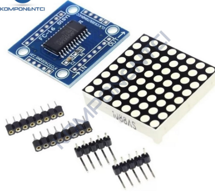
I've soldered 4 MAX7219 modules together and uploaded the code below to my ESP32 Core Board V2. However, the "Hello" text appears incorrectly, as shown in the photo. Written in the last module should actually be at the beginning. I've tried many methods and solutions, but I couldn't fix it. Has anyone encountered this issue before?

include <WiFi.h>
#include <NTPClient.h>
#include <WiFiUdp.h>
#include <MD_Parola.h>
#include <MD_MAX72xx.h>
#include <SPI.h>

// Bağlantı pinleri
#define DATA_PIN 23  // DIN
#define CS_PIN   5   // CS / LOAD
#define CLK_PIN  18  // CLK

// Kaç modül var?
#define MAX_DEVICES 4

// Donanım tipi
#define HARDWARE_TYPE MD_MAX72XX::FC16_HW

MD_Parola parola = MD_Parola(HARDWARE_TYPE, DATA_PIN, CLK_PIN, CS_PIN, MAX_DEVICES);

void setup() {
  // Parola başlat
  parola.begin();
  
  parola.displayText("Hello", PA_CENTER, 0, 0, PA_PRINT, PA_NO_EFFECT);
  parola.displayAnimate();  
}

void loop() {
  if (parola.displayAnimate()) {
  }
}

You are missing the "#" in front of this...

Remove parts of the code you do not need...

Try replacing the above with this

#define HARDWARE_TYPE MD_MAX72XX::GENERIC_HW

Try change this line:
//#define HARDWARE_TYPE MD_MAX72XX::FC16_HW
to this:
#define HARDWARE_TYPE MD_MAX72XX::PAROLA_HW

I tested your code in the simulator and it looked the same as your display, so I changed the HARDWARE line and it worked correctly.

See simulator:

Actually, I have # in my code but I didn't copy. My mistake.

I will develeop another project then I will need these lib.

I tried but, text appears wrong again.

When I use Parola_Hw, the text appears mirrored.

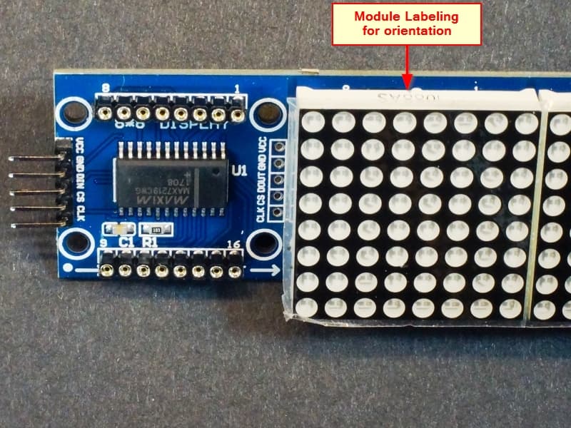
Does the white part LED matrix have a direction?
I soldered them all in the same direction.
Could I should soldered them in the opposite direction?
I am not sure the direction.
@ruilviana

Ref: MAX7219 8x8 Dot Matrix (x4) Red Display Module - ProtoSupplies

I had a 50% chance. I soldered it wrong. :frowning:
I didn't know matrix had a direction.
I have to remove 64 solders and re-solder them.
I will try tomorrow and inform here. Thank you dude. @ruilviana

Maybe. Hold off until you are sure this isn't a problem that can be fixed in software, then weigh which option sounds like more fun.

I'd work all day to avoid the soldering job… and the risk it might be doing.

a7

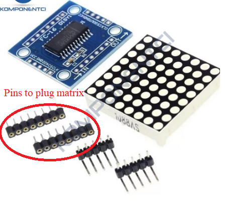
Did you solder the matrix directly to the PCB?
Didn't you use the pins that came with the kit?
If you used the pins, simply pull the die to remove and invert.

It looks like this library might help. " [MD_MAX72xx] "
I'll try the example: " [MD_MAX72xx_HW_Mapper.ino]"

  • HW_DIG_ROWS – set to 1 if MAX72xx digits are mapped to rows in the matrix
  • HW_REV_COLS – set to 0 for normal orientation with col 0 on the right, set to 1 if reversed
  • HW_REV_ROWS – set to 0 for normal orientation with row 0 at the top set to 1 if reversed

See if any of these settings resolve your issue:

For those of you who are still struggling, replace the PAROLA_HW with your appropriate type on this line:

#define HARDWARE_TYPE MD_MAX72XX::PAROLA_HW

PAROLA_HW
Use the Parola style hardware modules.

GENERIC_HW
Use 'generic' style hardware modules commonly available.

ICSTATION_HW
Use ICStation style hardware module.

FC16_HW
Use FC-16 style hardware module.

#define HARDWARE_TYPE MD_MAX72XX::ICSTATION_HW
with this definition reversed, I think it will work in your case.

See in the simulator, it was inverted with my HW.

You don't need NTPClient.h on an ESP32 as the ESP32 comes with a NTP implementation already.
See:

@ruilviana Hello Dude,
I just tried your advice and my problem is solved. I really thank you.
I have never heard Wokwi, It's looks really good platform. I will use this website, I also thank you for this.

I've complete my clock project thanks to you.
Now, I can see clock, date, day, humidity and temperature on the matrix led.
It will be my desk clock.

Also thank you everyone for your support.

This topic was automatically closed 180 days after the last reply. New replies are no longer allowed.