Hello All,
Many thanks for viewing any input appreciated.
I am attempting to generate PWM output from the Mega2560 and get my MCP4725 DAC to generate a sign wave, full sketch attached below.
Sketch uploads and runs fine. Output DC voltage from DAC oscillates only between 2.3 to 2.6V. i.e. I do not see the full range in the region of 0 - 5V I expect using this sketch. Could this be a faulty DAC typically?
Attempted to attach image below to show simplicity of setup utilising the I2C protocol (5V-VCC, GND-GND, SDA(PIN20)-SDA, SCL(PIN21)-SCL. DAC out connected to multimeter.

/******************************************************************************
MCP4725 Example Waveform Sketch
Joel Bartlett
SparkFun Electronics
Sept. 11, 2014
https://github.com/sparkfun/MCP4725_Breakout
https://learn.sparkfun.com/tutorials/mcp4725-digital-to-analog-converter-hookup-guide/all
This sketch takes data from a lookup table to provide
waveforms to be generated by the MCP4725 DAC.
Development environment specifics:
Arduino 1.0+
Hardware Version V14
This code is beerware; if you see me (or any other SparkFun employee) at the local,
and you've found our code helpful, please buy us a round!
Distributed as-is; no warranty is given.
This code builds off the sketch written by Mark VandeWettering, which can be found here:
http://brainwagon.org/2011/02/24/arduino-mcp4725-breakout-board/
*/
#include <Wire.h>//Include the Wire library to talk I2C
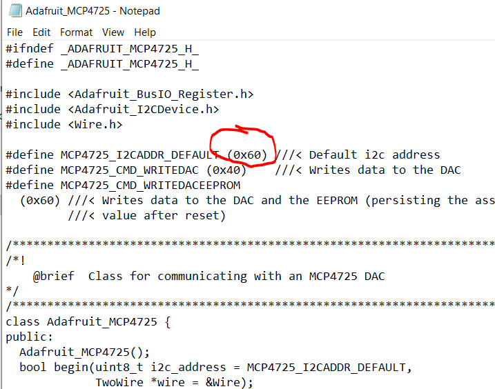
#include <Adafruit_MCP4725.h>
//This is the I2C Address of the MCP4725, by default (A0 pulled to GND).
//Please note that this breakout is for the MCP4725A0.
#define MCP4725_ADDR 0x60
//For devices with A0 pulled HIGH, use 0x61
//Sinewave Tables were generated using this calculator:
//http://www.daycounter.com/Calculators/Sine-Generator-Calculator.phtml
int lookup = 0;//varaible for navigating through the tables
int sintab2[512] =
{
2048, 2073, 2098, 2123, 2148, 2174, 2199, 2224,
2249, 2274, 2299, 2324, 2349, 2373, 2398, 2423,
2448, 2472, 2497, 2521, 2546, 2570, 2594, 2618,
2643, 2667, 2690, 2714, 2738, 2762, 2785, 2808,
2832, 2855, 2878, 2901, 2924, 2946, 2969, 2991,
3013, 3036, 3057, 3079, 3101, 3122, 3144, 3165,
3186, 3207, 3227, 3248, 3268, 3288, 3308, 3328,
3347, 3367, 3386, 3405, 3423, 3442, 3460, 3478,
3496, 3514, 3531, 3548, 3565, 3582, 3599, 3615,
3631, 3647, 3663, 3678, 3693, 3708, 3722, 3737,
3751, 3765, 3778, 3792, 3805, 3817, 3830, 3842,
3854, 3866, 3877, 3888, 3899, 3910, 3920, 3930,
3940, 3950, 3959, 3968, 3976, 3985, 3993, 4000,
4008, 4015, 4022, 4028, 4035, 4041, 4046, 4052,
4057, 4061, 4066, 4070, 4074, 4077, 4081, 4084,
4086, 4088, 4090, 4092, 4094, 4095, 4095, 4095,
4095, 4095, 4095, 4095, 4094, 4092, 4090, 4088,
4086, 4084, 4081, 4077, 4074, 4070, 4066, 4061,
4057, 4052, 4046, 4041, 4035, 4028, 4022, 4015,
4008, 4000, 3993, 3985, 3976, 3968, 3959, 3950,
3940, 3930, 3920, 3910, 3899, 3888, 3877, 3866,
3854, 3842, 3830, 3817, 3805, 3792, 3778, 3765,
3751, 3737, 3722, 3708, 3693, 3678, 3663, 3647,
3631, 3615, 3599, 3582, 3565, 3548, 3531, 3514,
3496, 3478, 3460, 3442, 3423, 3405, 3386, 3367,
3347, 3328, 3308, 3288, 3268, 3248, 3227, 3207,
3186, 3165, 3144, 3122, 3101, 3079, 3057, 3036,
3013, 2991, 2969, 2946, 2924, 2901, 2878, 2855,
2832, 2808, 2785, 2762, 2738, 2714, 2690, 2667,
2643, 2618, 2594, 2570, 2546, 2521, 2497, 2472,
2448, 2423, 2398, 2373, 2349, 2324, 2299, 2274,
2249, 2224, 2199, 2174, 2148, 2123, 2098, 2073,
2048, 2023, 1998, 1973, 1948, 1922, 1897, 1872,
1847, 1822, 1797, 1772, 1747, 1723, 1698, 1673,
1648, 1624, 1599, 1575, 1550, 1526, 1502, 1478,
1453, 1429, 1406, 1382, 1358, 1334, 1311, 1288,
1264, 1241, 1218, 1195, 1172, 1150, 1127, 1105,
1083, 1060, 1039, 1017, 995, 974, 952, 931,
910, 889, 869, 848, 828, 808, 788, 768,
749, 729, 710, 691, 673, 654, 636, 618,
600, 582, 565, 548, 531, 514, 497, 481,
465, 449, 433, 418, 403, 388, 374, 359,
345, 331, 318, 304, 291, 279, 266, 254,
242, 230, 219, 208, 197, 186, 176, 166,
156, 146, 137, 128, 120, 111, 103, 96,
88, 81, 74, 68, 61, 55, 50, 44,
39, 35, 30, 26, 22, 19, 15, 12,
10, 8, 6, 4, 2, 1, 1, 0,
0, 0, 1, 1, 2, 4, 6, 8,
10, 12, 15, 19, 22, 26, 30, 35,
39, 44, 50, 55, 61, 68, 74, 81,
88, 96, 103, 111, 120, 128, 137, 146,
156, 166, 176, 186, 197, 208, 219, 230,
242, 254, 266, 279, 291, 304, 318, 331,
345, 359, 374, 388, 403, 418, 433, 449,
465, 481, 497, 514, 531, 548, 565, 582,
600, 618, 636, 654, 673, 691, 710, 729,
749, 768, 788, 808, 828, 848, 869, 889,
910, 931, 952, 974, 995, 1017, 1039, 1060,
1083, 1105, 1127, 1150, 1172, 1195, 1218, 1241,
1264, 1288, 1311, 1334, 1358, 1382, 1406, 1429,
1453, 1478, 1502, 1526, 1550, 1575, 1599, 1624,
1648, 1673, 1698, 1723, 1747, 1772, 1797, 1822,
1847, 1872, 1897, 1922, 1948, 1973, 1998, 2023
};
void setup()
{
Wire.begin();
// Set A2 and A3 as Outputs to make them our GND and Vcc,
//which will power the MCP4725
pinMode(A2, OUTPUT);
pinMode(A3, OUTPUT);
digitalWrite(A2, LOW);//Set A2 as GND
digitalWrite(A3, HIGH);//Set A3 as Vcc
}
//---------------------------------------------------
void loop()
{
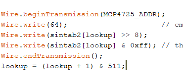
Wire.beginTransmission(MCP4725_ADDR);
Wire.write(64); // cmd to update the DAC
Wire.write(sintab2[lookup] >> 4); // the 8 most significant bits...
Wire.write((sintab2[lookup] & 15) << 4); // the 4 least significant bits...
Wire.endTransmission();
lookup = (lookup + 1) & 511;
}The ultimate goal is to use PWM input to Arduino from a radio control receiver to generate DC output voltage to control a hydraulic pump remotely.
Thanks