I have two MCP4725 DACs connected on the I2C bus. I connected them as the data sheet says and all was great and dandy, and even ran a triangle wave example and viewed it on an oscope.
It was working for a few hours and outputting the voltages correctly but then I connected the vout and gnd of the second DAC to a signal conditioner that takes in a 0-5V signal. The DACs stopped working. Once I realized it wasn't working, I reverted everything back, meaning I just disconnected vout and gnd from the conditioner and measured the output which is now stuck at roughly 2.5V. Same code and wiring which was working before. And even though I only wired one DAC to the conditioner BOTH now do not output different voltages just stuck at around a constant 2.5V .
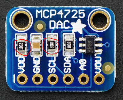
Do your breakout boards have realistic I2C pull-ups on board? At least 4.7k? If not, I’d add pull-ups to the breadboard as the Mega has 10k pull-ups by default which may be your problem. You should have at least one 100nf bypass cap on the mcp4725’s as well.
If you have the Sparkfun breakouts, the necessary parts are already in place. Cannot tell what you have with the Fritzing finger painting.
You must only connect voltages that are in the range of 0V to 5V of the DAC's supply. A separate supply could be floating at any voltage w.r.t. the Arduino circuit.
WattsThat:
Do your breakout boards have realistic I2C pull-ups on board? At least 4.7k? If not, I’d add pull-ups to the breadboard as the Mega has 10k pull-ups by default which may be your problem. You should have at least one 100nf bypass cap on the mcp4725’s as well.
If you have the Sparkfun breakouts, the necessary parts are already in place. Cannot tell what you have with the Fritzing finger painting.
You must only connect voltages that are in the range of 0V to 5V of the DAC's supply. A separate supply could be floating at any voltage w.r.t. the Arduino circuit.
Did you common the grounds?
The 24V supply only powers the signal conditioner. It is completely isolated from the arduino and DAC.
Grumpy_Mike:
Did you connect A0 differently on the two DACs? One you need to connect to 5V and the other you need to connect to ground.
With the ground of the 24V supply?
On one of them yes I connected A0 to 5V but on the other I did not connect A0 to anything. However, that being said it was working for quite a bit that way.
Sorry! No I did not tie the ground of the DACs to the 24V supply ground. I only connected the grounds of the DACs to the 5V power supply gnd and left it that way. The 5v supply ground was also separate of the 24v supply ground.
Hi,
Have you run the I2C Scanner code to see if the two DACs are responding?
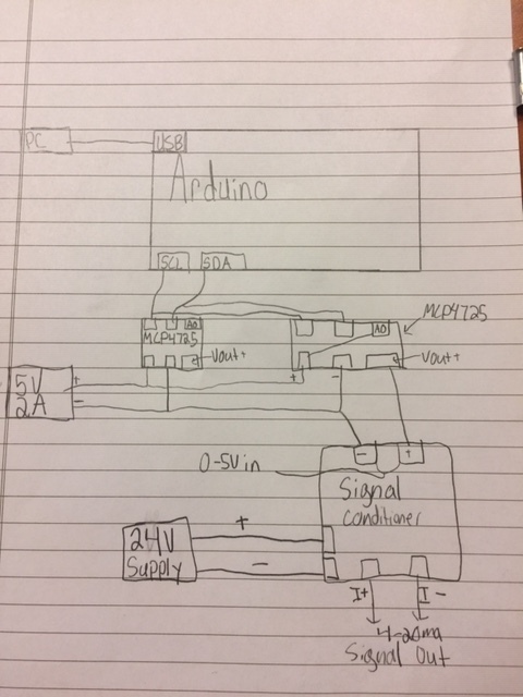
Can you draw a circuit diagram of your complete project, including the conditioners and how they are powered please?
Just a picture of a hand drawn circuit will speak volumes.
TomGeorge:
Hi,
Have you run the I2C Scanner code to see if the two DACs are responding?
Can you draw a circuit diagram of your complete project, including the conditioners and how they are powered please?
Just a picture of a hand drawn circuit will speak volumes.
Thanks.. Tom...
Hi Tom, Uploaded a rough photo! Thanks in advance !
Also have not had the chance to run the I2C scanner yet.
WattsThat:
Ether your schematic is missing important connections or:
There is no common connection (0V, GND) shown between the DAC's and the Arduino. That will not work.
The 5V 2A supply as shown is totally unnecessary, the DAC boards can be powered by 5V output of the Arduino.
The signal conditioner is galvanically isolated so no issues there between the Arduino & DAC's and whatever is being controlled.
The schematic is rough but it is how I wired it. I did not know the DAC must share a common with the arduino and will make sure to do that. That being said, though why would that cause an issue especially after it ran for hours fine? Thanks, Alex.
But why would they both be fried if I only connected one?
Because they are both connected through the I2C lines. Excess voltage can be spread thorough a circuit. You might have even blown the I2C lines on the Arduino.
That being said, though why would that cause an issue especially after it ran for hours fine?
Because functioning fine is no indication that the circuit is fine. It could have been chipping away at what ever blew up or it could be that something became loose on a the breadboard and pushed it over the edge.
Once you make serious errors in a design all bets are off and there is little point in worrying about the exact mechanism that caused failure. You will not learn anything useful if you know anyway. Just don't make those fundamental errors again.
Grumpy_Mike:
Because they are both connected through the I2C lines. Excess voltage can be spread thorough a circuit. You might have even blown the I2C lines on the Arduino.
Because functioning fine is no indication that the circuit is fine. It could have been chipping away at what ever blew up or it could be that something became loose on a the breadboard and pushed it over the edge.
Once you make serious errors in a design all bets are off and there is little point in worrying about the exact mechanism that caused failure. You will not learn anything useful if you know anyway. Just don't make those fundamental errors again.
Fair enough. However could I get an explanation on to why the ground of the DAC needs to be tied to the arduino ground? Especially when its being powered from its own supply. Thats the part I cant wrap my head around. Thanks
Try changing address of your dac, I had the same problem. So I connected A0 pin with ground and set the address to 0x60. It worked properly. It looks like the default voltage is 2.5v.