I am at a project, in which I need to use a big buzzer/beep at specific time.
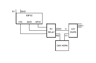
I am using ESP32 and sending signal to buzzer through 5v relay module which is having inbuilt optocoupler itself.
For that I am using a 5v buzzer, but due to low noise in open area, it is not of appropriate use.
Now I using a 12v car horn, which is having a nice big sound.
I connected it as per image given below.
But whenever horn makes sound, ESP32 gets malfunction.
While running code, ESP32 is having few variables for other operations.
Serial monitor started showing change of those veriables on every trigger of relay.
This happens only when using car horn, and not when using 5v small buzzer.
Preliminary power source of relay was through ESP32 itself, but even after changing it through external power source, issue continous
I used a flyback diode (1N4007) at VCC and GND of 5v relay, still no use
As per my assumption, 12v current comes back through signal gpio and disturbs ESP32
Modern car horns are usually electric, driven by a flat circular steel diaphragm that has an electromagnet acting on it in one direction and a spring pulling in the opposite direction. The diaphragm is attached to contact points that repeatedly interrupt the current to that electromagnet causing the diaphragm to spring back the other way, which completes the circuit again. This arrangement opens and closes the circuit hundreds of times per second, which creates a loud noise like a buzzer or electric bell, which sound enters a horn to be amplified.
A rule to remember: Assume the load is povered and current flows. When the driver, a relay, a transistor, swiches off the current through the load must be able to continue to release the magnetic field.
That makes the anode connects to the low side of the load and the cathode to the high side. The shorter distance between load and diode, the better.
@jremington and @JohnLincoln are correct. The reason some of the smaller diodes work is they can handle the surge current coming back from the inductor. The higher the frequency the more pulses the more RMS current. Undersizeing the diode is heading for future problems.
Your processor is more then likely failing because of EMI coming from the horn and its associated wireing. You can try adding a capacitor across the horn to see if that helps. Keep the power leads 90 degrees from the logic leads, if they run parallel that will couple a lot of noise into the processor.
This sounds like it is EMI, either conducted or radiated. While I can't confirm this is the problem without more information, I also can't rule it out. Most MOS logic circuits are fast and sensitive to edge transitions. Minimizing lead lengths (which act as antennas) to less than 10 inches (25 cm) is crucial, as longer leads can pick up frequencies up to about 750 MHz, not accounting for reflections and other effects. Tips to Reduce EMI:
Keep Connections Short: Both transmitters and receivers are affected by antenna length—longer antennas have greater gain and can pick up more interference. Use the KISS principle: Keep It Short & Simple. 2. Avoid Parallel Lines: Ensure power and logic lines are not running parallel to each other to minimize crosstalk and interference. 3. Use a Zero-Crossing Solid-State Relay on AC circuits: This can be a simple and effective solution to reduce EMI, especially when dealing with AC loads.
Historical Context: This issue has been known since the early 1960s with TCTL (Transistor-Coupled Transistor Logic), later known as TTL (Transistor-Transistor Logic). It prompted the development of line drivers and other technologies to manage EMI.
For further reading on related topics, check out these resources:
• Triac Principles and Circuits, Part 1: Learn about triacs, which are often used in switching applications and can be susceptible to EMI.
Read Part 1
• Triac Principles and Circuits, Part 2: This article continues exploring triac applications and EMI considerations.
Read Part 2
• Arduino Forum Discussion on Flashing LEDs: An example of EMI considerations in a practical Arduino project.
• Good Read: https://www.nutsvolts.com/magazine/article/September2015_HamWorkbench?
• Good Read: Audio Systems Group, Inc. Publications
A diodes across the electromagnet used in a horn might not works as intended because it will act as a slug, severely slowing the vibration. By providing a path for the current the magnesium decays more slowly, effecting a slowing of the vibration.
Have you tried switching another load, like a filament lamp or a another simple resistive load?
If that cured the problem, then you could be fairly certain that it's the horn causing the problem.
Arduinos or similar can drive buzzers or speakers, using appropriate circuits, without trouble, but the one you have chosen is going to cause problems.
If you must use that type, then look into ways of reducing EMI, shielding, twisted wire cable.