Thank you all for the work on the library! Library works great!
Please tell me if there any function to enable / disable (on/off) the screen? Ready to listen to any advice and recommendations! I have 3.95 mcufriend shield... Thanks!
Thank you all for the work on the library! Library works great!
Please tell me if there any function to enable / disable (on/off) the screen? Ready to listen to any advice and recommendations! I have 3.95 mcufriend shield... Thanks!
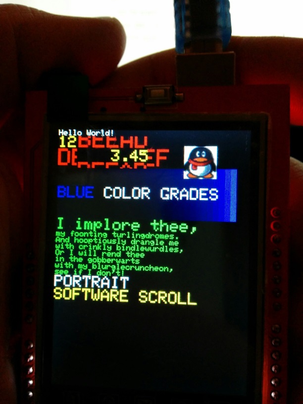
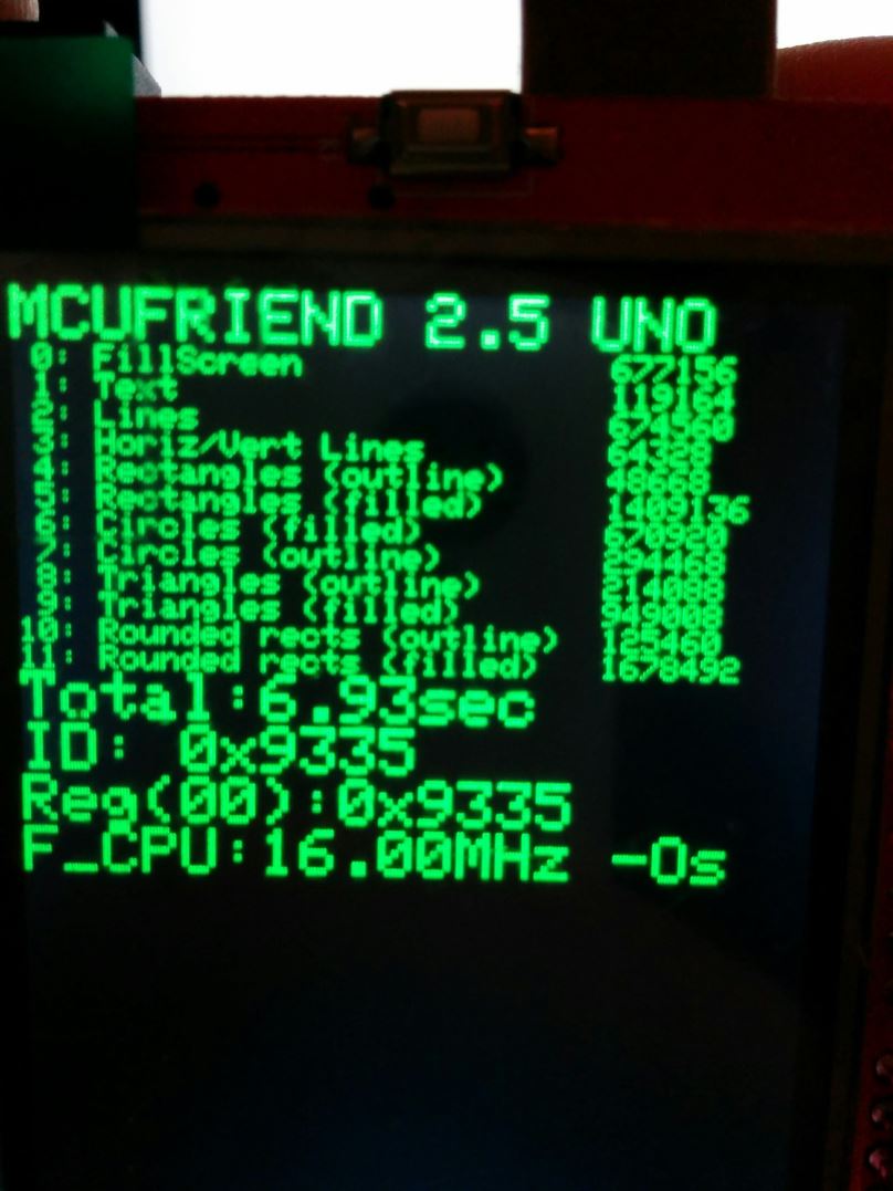
I ran the graphictest_kbv and it seems to work fine on my ili9335. The benchmark runs in 6.93 seconds (see attached picture).
As you said, "color band scroll" doesn't work.
"Software scroll" scrolls only a rectangle under "Hello world" (again, see picture). Is this normal? If yes, mark it "tested"!
Thanks for your report. Yes, both JPEGs look correct. I will update the "tested" list.
The reason for this odd window for "software scroll" is for compatibility. ( if the sketch is running on tiny 128x128 displays with different library)
If you change the #if in the sketch, you can use a more intuitive demo of the scroll.
But it is out of view on a small screen.
David.
tlk888:
Please tell me if there any function to enable / disable (on/off) the screen? Ready to listen to any advice and recommendations! I have 3.95 mcufriend shield... Thanks!
No, I do not have a method for sending the controller to sleep or on/off.
It is easy to do with "modern" controllers like the ILI9488. It will make little difference to the power consumption.
Most current goes to the backlight. There is no way to turn this off without hacking the shield.
You would need to switch the 5V pin.
Most of these shields use the 5V pin from the Arduino to supply the backlight.
They use the 3.3V pin from the Arduino for the controller logic.
Cut the trace between 5V pin and the shield LDO regulator.
Place a 500mA PNP transistor between 5V and LDO.
Control the transistor with the (unused) A5 pin via a resistor to the base.
UNTESTED. Do any mods at your own risk. The backlights take 100mA - 200mA.
David.
I have mcufriend 2.4" ST7781
I ran you code in the post #1
1st:
I got this error:
graphictest_kbv.ino:19:29: fatal error: Adafruit_TFTLCD.h: No such file or directory
compilation terminated.
Error compiling.
Then, I tried these modifications:
Uncommented:
#include <MCUFRIEND_kbv.h>
MCUFRIEND_kbv tft;
Commented:
//#include <Adafruit_TFTLCD.h>
//Adafruit_TFTLCD tft(LCD_CS, LCD_CD, LCD_WR, LCD_RD, LCD_RESET);
And got this message:
Sketch uses 32,228 bytes (99%) of program storage space. Maximum is 32,256 bytes.
Global variables use 1,907 bytes (93%) of dynamic memory, leaving 141 bytes for local variables. Maximum is 2,048 bytes.
Low memory available, stability problems may occur.
And ...
![]()
yaayee wow you are a hero
I'm really happy.
That's so nice.
Thank you so much,
Oops. It looks as if I put the wrong "graphictest_kbv.ino" sketch into the ZIP.
I have replaced the ZIP with a corrected version. And put the "corrected" sketch as a separate attachment.
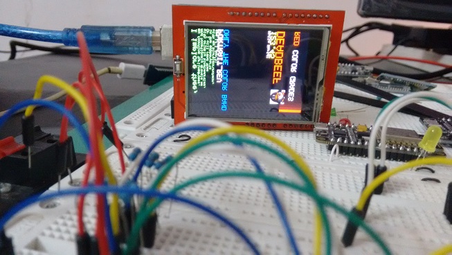
I am a little worried by your JPEG. It is displaying in PORTRAIT_REV mode but the directions are completely wrong. Arduino v1.6.6 reports for a UNO:
Sketch uses 31,508 bytes (97%) of program storage space. Maximum is 32,256 bytes.
Global variables use 1,904 bytes (92%) of dynamic memory, leaving 144 bytes for local variables. Maximum is 2,048 bytes.
Low memory available, stability problems may occur.
Yes, I have tried to squeeze as much as I can into the test sketch. 99.99% Flash is perfectly safe. 92% SRAM should be safe. You definitely do not want to risk more.
That is the reason for the "graphictest_slim.ino" sketch.
The standard sketch will not fit in a Leonardo or even a Duemilanove.
You can remove Serial, Floating Point, ... to reduce the Flash memory.
You can reduce the size of the software scroll buffer to reduce the SRAM memory.
Note that the ST7781 is the least powerful controller. It has a bug in its "vertical scroll" hardware.
That is why the Scroll tests do not operate on your board.
David.
David, thanks for fast answer and sorry for my bad english. ![]()
david_prentice:
Most current goes to the backlight. There is no way to turn this off without hacking the shield.
I thought exactly the same, but I'm not versed in microelectronics.
david_prentice:
You would need to switch the 5V pin.Most of these shields use the 5V pin from the Arduino to supply the backlight.
They use the 3.3V pin from the Arduino for the controller logic.Cut the trace between 5V pin and the shield LDO regulator.
Place a 500mA PNP transistor between 5V and LDO.
Control the transistor with the (unused) A5 pin via a resistor to the base.
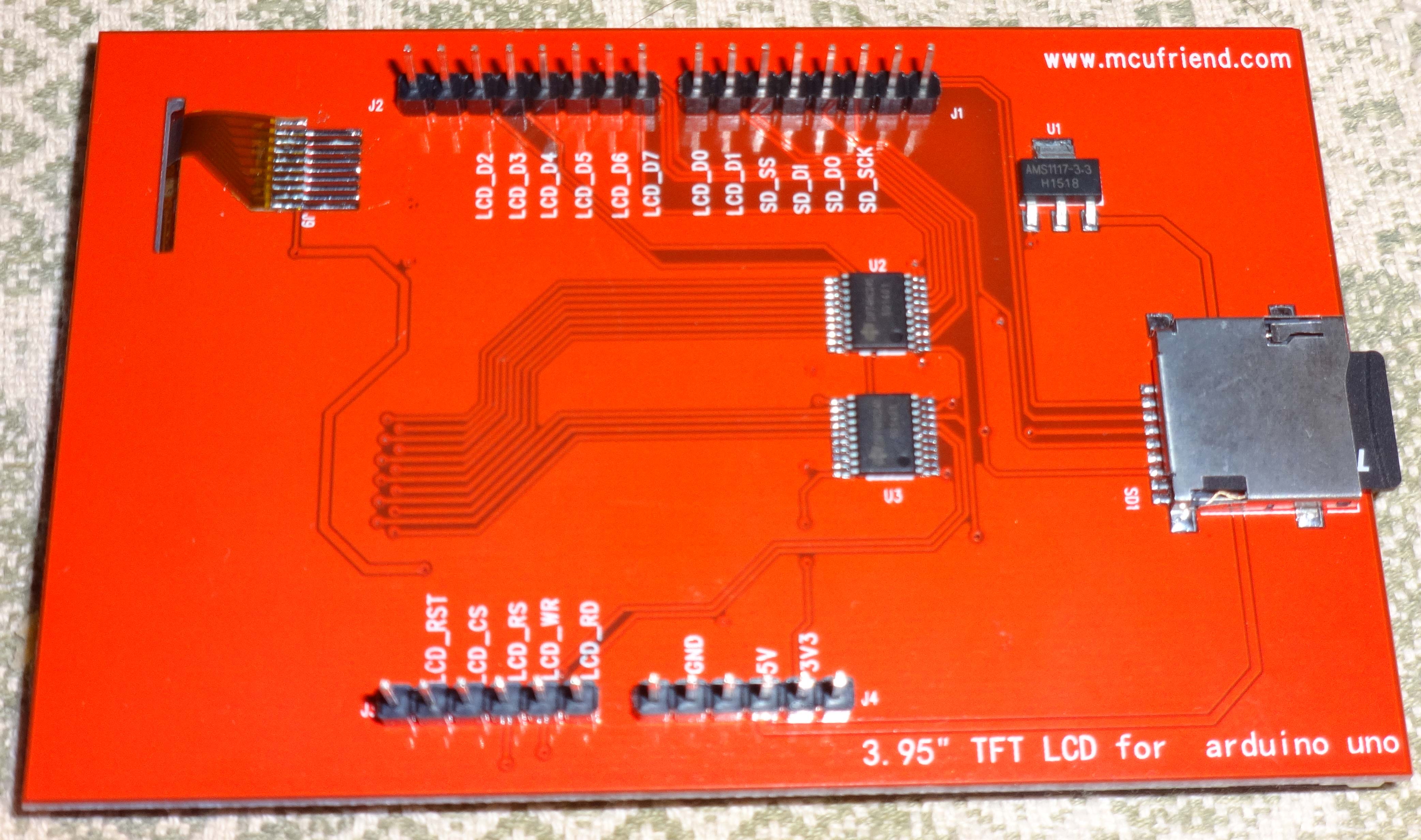
You can look at the attached photo, and tell how and what to do in my case?
I connect this shield to mega2560 with the wires, so I can insert an additional circuit with a transistor before 5V connection.
Which of the inexpensive transistor can you advise?
david_prentice:
UNTESTED. Do any mods at your own risk. The backlights take 100mA - 200mA.
I completely understand. Thank you very much for your help!
Any PNP transistor with a max collector current of 500mA or so will be fine.
I looked at what transistors I have. I seem to have several BC212L that are probably 30 yrs old.
Looking up the data. It is 300mA max. With a min hFE of 50. i.e. 4mA base current for 200mA.
So a 1k0 base resistor would switch it on.
If you are buying a new transistor, look for a 500mA PNP with hFE > 100. Look for a plastic case like TO92.
You can see the pcb trace that goes from 5V pin to U1. It looks easy to cut.
You can get at A5 pin by soldering on to the top of the header pin.
Glue the transistor and base resistor to the pcb with some epoxy.
Connect up by soldering some fine wire from A5 to the base resistor.
If you do not understand this, you should not attempt the mod.
I have not tried it.
David.
Yes, of course I downloaded the new sketch, it works very beautiful.
Now, I want to start learning C++ ![]()
Regards,
david_prentice:
Any PNP transistor .....
...If you do not understand this...
I'm understand and try to mod shield next week! Thanks very much for your advise!
And I think, this instruction may be helpful for others... Thanks!
What is the basic structures of programming a TFT display?
Such a big program, like this one which exceeds 30kb of flash memory.
The example sketch is at the limit of a UNO's memory. read message #45.
Regarding program structure, the other examples are a lot smaller.
There are hundreds of "Adafruit-style" examples. They should all work with this library. The only important lines are:
#include <Adafruit_GFX.h>
#include <MCUFRIEND_kbv.h>
MCUFRIEND_kbv tft;

uint16_t ID;

void setup(void)
{
    ID = tft.readID();  // you must detect the correct controller
    tft.begin(ID);      // everything will start working
    tft.fillScreen(0x001F);    //BLUE
    tft.print("Hello World");
}

void loop(void)
{
}
This was 10744 bytes (on my current un-released version). It may be different for you.
The purpose of "example" programs is to show you what you can do.
You write your own applications. When you are unsure how to draw a circle or print a message, you look at the example to see what was done.
It should be possible to fit most regular apps into a UNO.
However you need to be aware that loading big Fonts or bitmaps will use lots of Flash memory.
David.
Hi everyone
I'm trying to make the resistive touchscreen work with the arduino due, but I'm new to this arduino stuff so I'm having a hard time understanding what I need to do or even if its possible...
I have the 3.95'' TFT LCD ili9488 from mcufriend like this one:
http://www.aliexpress.com/item/3-5-inch-TFT-Touch-LCD-Screen-Display-Module-For-Arduino-UNO-R3-HIGH-QUALITY-Free/1854595985.html
I don't have any shield, just the lcd directly plugged into the due...
Anyone knows how to make the touchscreen work with the due?
Your display is a shield. You plug it directly into your UNO (or DUE).
The regular <TouchScreen.h> or <TouchScreen_due> library do not work with the shared pins.
One day I will write / publish a version that does work with the shield.
Meanwhile, I suggest that you plug it into a UNO.
David.
I thought you called the "shield" those intermediate boards you plug between the display and the arduino... my bad...
Ok thanks, I only have the DUE so I'm gonna have to keep researching... hopefully you'll not keep waiting for too long hehe.
Will you publish the solution here?
The board that "plugs into" the Arduino is called a Shield.
The intermediate board is called an "Adapter Shield". e.g. the ColdTears adapter shield for regular 40-pin TFT displays.
The Mcufriend MEGA2560 display shields have a separate Touch Controller chip and should work fine with UTFT and UTouch libraries. Unfortunately, the microSD does not work reliably.
No, I have no plans for writing a Touch library for the Due.
Meanwhile, you could buy a Uno clone.
David.
Hello, David,
Thanks for your great job!
Only owing to your topic i have started my LCD shield with chip ST7789V.
Finally i got a correct displaying in scketchs:
aspect_kbv
graphictest_kbv
LCD_ID_readreg
readpixel_kbv
scroll_kbv
testcard_kbv
But i still can not use touchscreen:
tftpaint_shield_kbv
TouchScreen_Calibr_kbv
UTouch_Calibr_kbv
are not working.
I suspect, that these sketchs are not optimized for ST7789V.
Could you give me information, where i can get correct library for touchscreen?
Thanks in advance!
I presume that you have a regular 2.4" Red shield or a 2.8" Blue shield.
The Touch is nothing to do with the TFT controller.
It is just a resistive screen that shares some pins with the controller.
Most of these shields use A1, 7 and A2, 6.
Unplug your shield and test the resistance between A1 and 7. It should be about 300 ohms.
If there is no resistance, try A1 with other digital pins. e.g. 6, 7, 8, 9.
When you have identified the actual pins used by the Resistive screen, you edit the TouchScreen_Calibr_kbv.ino sketch.
Please report back with your results.
David.
david_prentice:
... try A1 with other digital pins. e.g. 6, 7, 8, 9.
When you have identified the actual pins used by the Resistive screen, you edit the TouchScreen_Calibr_kbv.ino sketch...
Ok. understood.
Do you mean this records:
#define YP A1
#define YM 7
#define XM A2
#define XP 6
?
Do you have a Red or Blue shield?
Yes, you should read 300 ohms between YP and YM pins. It may be 1000 ohms.
If your screen is cracked, the resistance is broken too !
David.