I have sent you a PM. Sorry, it tells you how to install a special test branch. (after your effort to install the default Master branch)
David.
I have sent you a PM. Sorry, it tells you how to install a special test branch. (after your effort to install the default Master branch)
David.
one3rdnerd:
- I believe so, at least for non TFT screen related stuff.
- I haven't, what would I use to do this? I was using USB power. I have a power adapter also but its at a friends.
- When turning on it a kind of blue screen once turned on. When I load sketches like the graphicstest sometimes I get a flicker and that's it, one time I got coloured lines repeat for a while then back to original blue screen and the one time I managed to get the graphicstest to run in full.
Yes I am using 2.9.1-beta in IDE version 1.6.10
Thanks David
David
I suspect that you have a bad connection somewhere if sketches worked in the past. i.e. examine pcb with magnifying glass.
Here is the test sketch that I promised on Saturday: My Shield works best with configuration #0.
#include <Adafruit_GFX.h>
#include <MCUFRIEND_kbv.h>
MCUFRIEND_kbv tft;

// Assign human-readable names to some common 16-bit color values:
#define    BLACK   0x0000
#define BLUE    0x001F
#define RED     0xF800
#define GREEN   0x07E0
#define CYAN    0x07FF
#define MAGENTA 0xF81F
#define YELLOW  0xFFE0
#define WHITE   0xFFFF

void setup()
{
    Serial.begin(9600);
    uint16_t ID;
    ID = tft.readID(); //
    Serial.print("ID = 0x");
    Serial.println(ID, HEX);
    if (ID == 0xD3D3) ID = 0x9481; // write-only shield
    tft.begin(ID);
    tft.setRotation(1); //LANDSCAPE
    tft.fillScreen(BLACK);
    tft.setTextSize(2);
    tft.setTextColor(YELLOW, BLACK);
    tft.setCursor(0, 0);
    tft.println("This program will step through");
    tft.println("different power settings for an ILI9481");
    tft.println("Please do not run this if not ILI9481");
    Serial.println("This program will step through");
    Serial.println("different power settings for an ILI9481");
    Serial.println("Please do not run this if not ILI9481");
    const char *colorname[] = { "BLUE", "GREEN", "RED", "GRAY" };
    uint16_t colormask[] = { 0x001F, 0x07E0, 0xF800, 0xFFFF };
    uint16_t dx, rgb, n, wid = tft.width(), ht = 40, y = 100;
    dx = wid / 32;
    for (uint8_t aspect = 0; aspect < 4; aspect++ ) {
        for (n = 0; n < 32; n++) {
            rgb = n * 8;
            rgb = tft.color565(rgb, rgb, rgb);
            tft.fillRect(n * dx, y, dx, ht, rgb & colormask[aspect]);
        }
        tft.setTextColor(colormask[aspect], BLACK);
        tft.setCursor(0, y + 12);
        tft.print(colorname[aspect]);
        y += ht;
    }
}

// every entry MUST be the same size
uint8_t ILI9481_regValues[] = {
    0xD0, 3, 0x07, 0x42, 0x18,  // Set Power [00 43 18] x1.00, x6, x3
    0xD1, 3, 0x00, 0x07, 0x10,  // Set VCOM  [00 00 00] x0.72, x1.02
    0xD2, 2, 0x01, 0x02,        // Set Power for Normal Mode [01 22]
    0xC5, 1, 0x03,      //Frame Rate [03]
};
uint8_t ILI9481_PVI35_regValues[] = {
    0xD0, 3, 0x07, 0x41, 0x1D,  // Set Power [00 43 18]
    0xD1, 3, 0x00, 0x2B, 0x1F,  // Set VCOM  [00 00 00] x0.900, x1.32
    0xD2, 2, 0x01, 0x11,        // Set Power for Normal Mode [01 22]
    0xC5, 1, 0x03,      //Frame Rate [03]
};
uint8_t ILI9481_CPT29_regValues[] = {
    0xD0, 3, 0x07, 0x42, 0x1C,  // Set Power [00 43 18]
    0xD1, 3, 0x00, 0x02, 0x0F,  // Set VCOM  [00 00 00] x0.695, x1.00
    0xD2, 2, 0x01, 0x11,        // Set Power for Normal Mode [01 22]
    0xC5, 1, 0x03,      //Frame Rate [03]
};
uint8_t ILI9481_AUO317_regValues[] = {
    0xD0, 3, 0x07, 0x40, 0x1D,  // Set Power [00 43 18]
    0xD1, 3, 0x00, 0x18, 0x13,  // Set VCOM  [00 00 00] x0.805, x1.08
    0xD2, 2, 0x01, 0x11,        // Set Power for Normal Mode [01 22]
    0xC5, 1, 0x03,      //Frame Rate [03]
};
uint8_t ILI9481_CMO35_regValues[] = {
    0xD0, 3, 0x07, 0x41, 0x1D,  // Set Power [00 43 18] 07,41,1D
    0xD1, 3, 0x00, 0x1C, 0x1F,  // Set VCOM  [00 00 00] x0.825, x1.32 1C,1F
    0xD2, 2, 0x01, 0x11,        // Set Power for Normal Mode [01 22]
    0xC5, 1, 0x03,      //Frame Rate [03]
};
uint8_t ILI9481_RGB_regValues[] = {
    0xD0, 3, 0x07, 0x41, 0x1D,  // SETPOWER [00 43 18]
    0xD1, 3, 0x00, 0x2B, 0x1F,  // SETVCOM  [00 00 00] x0.900, x1.32
    0xD2, 2, 0x01, 0x11,        // SETNORPOW for Normal Mode [01 22]
    0xC5, 1, 0x03,      //SETOSC Frame Rate [03]
};
uint8_t ILI9481_RESET_regValues[] = {
    0xD0, 3, 0x00, 0x43, 0x18,  // SETPOWER [00 43 18]
    0xD1, 3, 0x00, 0x00, 0x0,  // SETVCOM  [00 00 00] x0.900, x1.32
    0xD2, 2, 0x01, 0x22,        // SETNORPOW for Normal Mode [01 22]
    0xC5, 1, 0x03,      //SETOSC Frame Rate [03]
};

uint8_t *configs[] = {
    ILI9481_regValues,
    ILI9481_CPT29_regValues,
    ILI9481_PVI35_regValues,
    ILI9481_AUO317_regValues,
    ILI9481_CMO35_regValues,
    ILI9481_RGB_regValues,
    ILI9481_RESET_regValues,
};

#define TFTLCD_DELAY8 0xFF
void init_table(uint8_t *table, int16_t size)
{
    uint8_t *p = (uint8_t *) table, dat[16];
    while (size > 0) {
        uint8_t cmd = *(p++);
        uint8_t len = *(p++);
        if (cmd == TFTLCD_DELAY8) {
            delay(len);
            len = 0;
        } else {
            for (uint8_t i = 0; i < len; i++)
                dat[i] = *(p++);
            tft.pushCommand(cmd, dat, len);
        }
        size -= len + 2;
    }
}

void loop()
{
    static uint8_t n = 0;
    uint8_t *p;
    uint8_t unlock = 0;
    if (++n >= sizeof(configs) / sizeof(*configs)) n = 0;
    p = configs[n];
    tft.setCursor(0, 300);
    tft.println("Using configuration :" + String(n) );
    Serial.println("Using configuration :" + String(n) );
    tft.pushCommand(0xB0, &unlock, 1);    //allow changes
    tft.pushCommand(0x28, NULL, 0);    //display off
    delay(100);
    init_table(configs[n], sizeof(ILI9481_regValues));
    delay(100);
    tft.pushCommand(0x29, NULL, 0);    //display on
    delay(5000);
}
David.
Edit. Run this sketch for a few minutes to determine the "best" configuration. Then switch off. The screen becomes noticeably hot. The backlight takes about 100mA. The controller probably takes about 30mA i.e. 100mW. This does not seem excessive. And I am surprised that I can feel any heat at all.
hello,
I bought a screen and connect to DUE, work fine with this library, but i need change the pinmaps, for now,I changed the pins analog to digital pins 22 23 24 25 26 and work fine, but how change de pins 2 3 4 5 6 7 8 9 to 27 forwards.
mcufriend_shield.h
#define RD_PORT PIOB            //PIOA
#define RD_PIN  26                //16
#define WR_PORT PIOA
#define WR_PIN  14               //24
#define CD_PORT PIOA
#define CD_PIN  15               //23
#define CS_PORT PIOD          //PIOA
#define CS_PIN  0                //22
#define RESET_PORT PIOD    //PIOA
#define RESET_PIN  1          //6
 // configure macros for data bus
#define BMASK         (1<<25)
#define CMASK         (0xBF << 21)
#define write_8(x)   {  PIOB->PIO_CODR = BMASK; PIOC->PIO_CODR = CMASK; \
                        PIOC->PIO_SODR = (((x) & (1<<0)) << 22); \
                        PIOC->PIO_SODR = (((x) & (1<<1)) << 20); \
                        PIOB->PIO_SODR = (((x) & (1<<2)) << 23); \
                        PIOC->PIO_SODR = (((x) & (1<<3)) << 25); \
                        PIOC->PIO_SODR = (((x) & (1<<4)) << 22); \
                        PIOC->PIO_SODR = (((x) & (1<<5)) << 20); \
                        PIOC->PIO_SODR = (((x) & (1<<6)) << 18); \
                        PIOC->PIO_SODR = (((x) & (1<<7)) << 16); \
					 }

#define read_8()      ( ((PIOC->PIO_PDSR & (1<<22)) >> 22)\
                      | ((PIOC->PIO_PDSR & (1<<21)) >> 20)\
                      | ((PIOB->PIO_PDSR & (1<<25)) >> 23)\
                      | ((PIOC->PIO_PDSR & (1<<28)) >> 25)\
                      | ((PIOC->PIO_PDSR & (1<<26)) >> 22)\
                      | ((PIOC->PIO_PDSR & (1<<25)) >> 20)\
                      | ((PIOC->PIO_PDSR & (1<<24)) >> 18)\
                      | ((PIOC->PIO_PDSR & (1<<23)) >> 16)\
                      )
#define setWriteDir() { PIOB->PIO_OER = BMASK; PIOC->PIO_OER = CMASK; }
#define setReadDir()  { \
                          PMC->PMC_PCER0 = (1 << ID_PIOB)|(1 << ID_PIOC);\
						  PIOB->PIO_ODR = BMASK; PIOC->PIO_ODR = CMASK;\
						}
#define write8(x)     { write_8(x); WR_ACTIVE; WR_STROBE; }
A shield has got fixed wiring. It just plugs in to your Due and I know that LCD_D1 is on digital#9 and LCD_CS is on Analog#3.
Do you intend to change all the pcb tracks on the shield?
If you tell me which pins you want to rewire, I will PM you with the changes.
i.e. do you want LCD_D2 on digital#27?
David.
Hi David,
Still not having much joy so I had an idea...
Can you recommend to me a) The best 3.5 inch non-touchscreen TFT I should get which is most compatible and supported by libraries and specifically your library and b) Same as A but a touchscreen version. I am in the UK so I suppose perhaps that factors into where I order it online.
If you want, since you are so helpful and contributing to the community I would happily post you this semi functional screen I have for free which you can keep, perhaps it will help you discover what is unique about it to help others in the future. You can private message me your details if you want me to do that. My email is david@pixelloop.org
Thanks
Ebay is a bit of a lottery.
There are Red 3.5" Uno shields that contain ILI9481, ILI9486, ... as well as the new "mystery controllers": 0x1511, 0x6814. These have a Resistive Touch Panel
The Blue 3.5" displays do not have a Touch Panel.
There are Red 3.5" Mega2560 shields that have a XPT2046 Touch controller.
The Blue 3.5" Mega2560 shields do not have a Touch Panel.
The Mega2560 shields are write-only. The Red ones have unreliable microSD due to massive series resistors.
The Blue microSD probably work fine.
The biggest problem is that you can never trust the Ebay Vendors. They post photos that do not match the items. They post inaccurate information. If I try to buy the exact same item from a punter's Ebay link, I often receive a different item. The same applies to BangGood or DealExtreme.
So I am not going to recommend anything. You will just have to hope and pray like everyone else.
There are also bare 3.3V modules, or 3.3V modules mounted on a pcb that require an Adapter Shield before you can use with an Arduino. I suggest that you avoid these.
In an ideal world, they could make both Uno and Mega2560 shields that work properly. i.e. using LV245 buffers instead of HC245 buffers. Access RD pin on both Uno and Mega2560. It would cost the Chinese an extra $0.20 to use the correct buffers. It would cost them nothing to provide honest information about which controllers are mounted.
David.
Okay, after 3 weeks my AliX 3.95" MCUFRIEND has been picked up.... ![]()
I HAD a slideshow sketch running on Bodmer's library (HX8357B) with my BangGood 3.2" 9481 screen so I just swapped screens and crossed my fingers.
It didn't work even when I reuploaded the sketch. So I tried a sketch for the Uno format 3.95" and (as expected) that didn't work either ![]()
It is NOT an "MCUFRIEND on a Uno" so I don't know if to post here or start a new thread "MCUFRIEND on a Mega"?
Somewhere in this thread I think I read that the library CAN(?) be made to work on a Mega format? ? ? ?
Maybe I should have avoided buying the new format altogether!? But I couldn't resist ![]() It was AUD12 so no big deal
It was AUD12 so no big deal ![]()
I might bite my tongue and contact the seller (Ha! Ha!) (LOL)
Here is the link if anyone is interested?
I got what I ordered - the Mega format but, unlike the BangGood screen it has a 6 bank(the power bank) and an 8 bank (0 to 7?) of pins instead of just the two pins for power....
Please indicate if I should start a new thread or continue here?
The link DOES claim it is an ILI9488? ? ? ? but we all know how reliable AliX is....
I'm in your hands.... ![]()
You have bought a Mega2560 shield with an 8-bit interface.
Q. How to distinguish Mega shield from a Uno shield:
A: the Mega shield has more pins.
Q. How to distinguish an 8-bit Mega shield from a regular 16-bit Mega shield:
A: either the 8-bit shield has fewer resistor packs or the 8-bit shield has fewer buffer chips.
You do not need to be an electronics expert to count pins or "major components" on a pcb.
The $64000 question is: Does the shield in your hand match the photos on the Aliexpress link?
David.
Is that US$ or AU$? ![]()
I confirm, what I have in my hot little hands is EXACTLY what is displayed in the link.... ![]()
I assume this means I continue in this thread?
The back of the shield, unusually has NO legends on the pins. ![]()
The "link" has a photo of a Uno Shield and a photo of a Mega Shield under the Product Description.
The Uno Shield has got legends on the pins e.g. SD_SCK
Both pcbs have got legends next to the components. e.g. U1 or RP2.
You certainly seem to choose Vendors with the most conflicting photos, text, ...
Have you really compared the number of Resistor Packs on your pcb with the Mega photos?
David.
Yes David,
I have looked at it, with my old eyes and a magnifying glass. There are 6 banks(?) (RP1 to RP6) of 4 labelled 103 and a single 103 (R1).
There is a missing capacitor C1. A regulator(?) U1 labelled AMS1117 3.3 DN628. A missing 8 legged chip U5. A 16 legged chip U2 labelled XPT2046 1609. And, of course, the microSD reader.
I haven't cut the stays holding the display to the PCB but will if it is any help.
The seller responded with an initialisation sequence but no driver Lcd_write_data or Lcd_write_com methods, just an Address_set method. The sequence doesn't match the style of UTFT, Adafruit, HX8357 or your libraries. The sequence is much like (if not exactly like) the ones I have seen on other AliX screens!?
I can post the coding or PM it to you if you wish. ![]()
Thanks for you interest. ![]()
Can you show me some clear example, please?
Some clear example of what?
The library comes with several examples.
It is best to run the graphictest_kbv.ino sketch and look for what sort of thing you want to draw.
e.g. circles, text, rectangles, colours, ...
Then look at the relevant testCircles(), testText(), ... functions.
Or just ask here.
Here is a simple sketch:
#include <Adafruit_GFX.h> // Hardware-specific library
#include <MCUFRIEND_kbv.h>
MCUFRIEND_kbv tft;

#define BLACK   0x0000
#define BLUE    0x001F
#define RED     0xF800
#define GREEN   0x07E0
#define CYAN    0x07FF
#define MAGENTA 0xF81F
#define YELLOW  0xFFE0
#define WHITE   0xFFFF

void setup()
{
    uint16_t ID = tft.readID();
    tft.begin(ID);        //must use correct ID
    tft.setRotation(1);   //Landscape
    tft.fillScreen(RED);
    tft.setTextSize(2);
    tft.setTextColor(WHITE, MAGENTA);
    tft.setCursor(0, 100);
    tft.println("Print with background");
    tft.setTextColor(YELLOW);
    tft.setCursor(0, 200);
    tft.println("Transparent print");
}

void loop()
{
}
David.
Edit. added the simple sketch
Why do you want to change anything? A shield plugs into your Due with every male finding its appropriate female.
A Due has got plenty of spare pins.
A Due operates the microSD perfectly in software. And almost as fast as regular hardware SPI on a Uno.
If you really need to create a non-standard interface, you should put it in the mcufriend_special.h file.
Yes, I can show you how to do that but first off, you should think about why you want to hack a ready-made shield.
David.
Oops. I misread you. I see that you have a Uno and not a Due.
mcufriend_shield.h:
#define USE_SPECIAL
mcufriend_special.h:
#define USE_JACKHMCD
...
#elif defined(__AVR_ATmega328P__)  && defined(USE_JACKHMCD)
#define RD_PORT PORTC
#define RD_PIN  0
#define WR_PORT PORTC
#define WR_PIN  1
#define CD_PORT PORTC
#define CD_PIN  2
#define CS_PORT PORTC
#define CS_PIN  3
#define RESET_PORT PORTC
#define RESET_PIN  4

#define BMASK    ((1<<0)|(1<<3))       //D8, D11
#define DMASK    (0xFC)
#define write8(x)     { \
                        PORTD = (PORTD & ~DMASK) | (x & DMASK);\
                        PORTB = (PORTB & ~BMASK) | ((x & 1) | ((x & 2) << 2)); WR_STROBE; }
#define read_8()      ( ((PIND & DMASK)|(PINB & 1)|((PINB & 8)>>2) )
#define setWriteDir() { DDRD |=  DMASK; DDRB |=  BMASK; }
#define setReadDir()  { DDRD &= ~DMASK; DDRB &= ~BMASK; }
#define write8(x)     { write_8(x); WR_STROBE; }
#define write16(x)    { uint8_t h = (x)>>8, l = x; write8(h); write8(l); }
#define READ_8(dst)   { RD_STROBE; dst = read_8(); RD_IDLE; }
#define READ_16(dst)  { uint8_t hi; READ_8(hi); READ_8(dst); dst |= (hi << 8); }

#define PIN_LOW(p, b)        (p) &= ~(1<<(b))
#define PIN_HIGH(p, b)       (p) |= (1<<(b))
#define PIN_OUTPUT(p, b)     *(&p-1) |= (1<<(b))

...
Untested.
David.
Instead of using D8, D9 you are using D8, D11. i.e. you are using PB3 instead of PB1. PB0 is unchanged.
You can always test your hardware with the LCD_ID_readreg sketch.
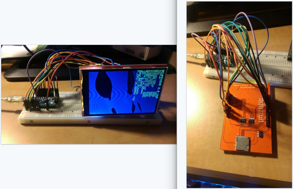
Hello, first of all i want to sat that everything works in my case ![]() (thank you for this awesome libray david_pentice!! good job) but Im wondering how A5 pin works.
(thank you for this awesome libray david_pentice!! good job) but Im wondering how A5 pin works.
Im using tft lcd 0x9481 (it is broken but it is prototype for now) and arduino nano connected as you see by wires. It is because i want to use RTC on I2C that usesA4(SDA) and A5(SCL). Im not using Sdcard or touch. A5 pin is free but A4 is used for lcd reset. When i disconnect this wire lcd goes white. Only way to get it back to working is to connect it to +5V as you advised earlier in this thread.
But im wondering if A4 pin is ready to use for I2C communication or I have to reconfigure it somewhere ? When I connect lcd reset wire to D12, D11, D10 pin wich is unused lcd does not work. How different is A4 from D12 ? I think it must be software configured somewhere. In your code I found something like int RST=A4 or #define RESET_OUTPUT PIN_OUTPUT(RESET_PORT, RESET_PIN) but i cannot find where RESET_PIN is defined.
Could you explain me how this mysterious A4 pin works ?
Snip off the LCD_RESET pin (A4) from the shield header.
Solder a 10k resistor from the top of the snipped shield header pin to the top of the 5V shield header pin.
The display should work just fine with "Software Reset" (0x01) command. You do not need to make any changes to sketches.
Plug the shield into a Uno or Mega.
Connect your I2C devices to the SDA, SCL pins.
I do not recommend using a Nano. What is the point of buying a shield if you do not use its male-female connectability?
Obviously you can just connect LCD_RESET pin to 5V via a 10k resistor without snipping a pin. But the snip and solder method makes your shield good for any proper Arduino.
Do you have a Red or Blue shield? The blue shields sometimes overheat. I am not sure why.
David.
Thank you for reply ! I attached picture. I have red board, and this violet cable is for lcd reset. But after some time bottom of lcd gets hot. Should i use 3V3 or 5V for lcd ?
So you suggest using tft on breakout board for arduino nano ? This is my first tft so i searched ebay for tft for arduino uno. I thought by doing this I will be sure that it works with my nano. Also i decided to connect some more things to arduino and using it as a shield would use all the free pins. But using it with uno and snipping off lcd reset pin is also a good idea ![]()
But anyway, ok i tried with 10k resistor yesterday and it works. Ahh, software reset with 0x01. So lcd reset wire just needs pull up restor for working (to have precise logic state)? A4 pin is working with lcd and D12 is not because of internal pull up resistor or in/out software configuration?
I do not have to make changes for sketches even though i found this #define RESET_IDLE PIN_HIGH(RESET_PORT, RESET_PIN) ? Why is it defined and used although software reset is used ?
You should connect every pin from the shield to the corresponding pin on your Nano. i.e. if the shield says 3V3 you connect it to the Nano's 3V3 pin. Likewise the 5V shield pin to the Nano's shield pin.
Why?
Uno clones are so cheap. A shield is always going to mate correctly. You always get good electrical connections.
I use Software Reset for the modern MIPI controllers. Old controllers like ILI9320 do not have Software Reset command. They all get the Hardware Reset. You do not need to change any library software.
You probably need to call Wire.begin() after tft.begin(). Try it for yourself. Then swap the order and see if it upsets TWI.
Oh, some new Uno clones come with SMD AVR and extra holes for header pins. And access to A6, A7 and extra headers for I2C
David.