Hello all,
This is my first post so please be kind if anything I ask is stupid. For my project, I want to display the RPM of my vehicle(VW T3, 1983) and other information on a dashboard display at a later date. Engine is a 4 cylinder waterboxer.
With the oscilloscope I found out that on the normal 12V net a peak in the height of approx. 1.2V occurs depending on the speed. The interval between the peaks at idle speed is 30ms.
Using the formula 1s/0.03s *60 /2 = 1000 rpm, this is a quite plausible value. The spacing of the peaks then decreases to 5ms at maximum rpm.
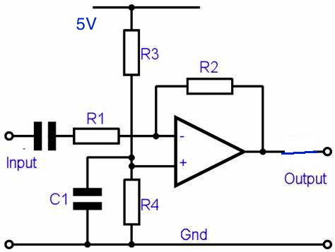
Now I thought about designing a high-pass filter that filters out the 12V DC component, leaving only the 1.2V peak. I would like to determine the distance between these peaks with my Arduino Nano on port A0 and the function AnalogRead() and some kind of Timer. With this information i could then calculate the rpm with the formula above. Unfortunately, I haven't found much information on how to measure the distance between the two 1,2V peaks on the anoglog input.
Since I am still relatively inexperienced, the programming is still a bit difficult for me. Is there anything to criticise about my approach or would you solve it differently?
Could you explain a bit more about how you identified these peaks? Were you using an oscilloscope?
I ask because I think the first thing I would do is check what this waveform looks like at other engine speeds - 2000rpm, 3000rpm, etc. Also, under different electrical loads, such as headlights, rear window demister, etc.
I'm not really clear why you are seeing any kind of signal as high as 1.2V on the cigar lighter that happens to be at crankshaft speed. I'm not sure I would rely on it, to be honest. There will be a crankshaft or camshaft sensor (or both) connected to the ECU, and you can intercept one of those easily enough. Probably end up being more dependable.
Thanks for your answer, it is pretty clear to me that there a multiple ways of getting an engine rpm. I'm just interested to solve it by getting the information about the input of the generator to the 12V net. In my eyes, this would be a very elegant solution.
I'm not sure about elegant, but that aside: is it dependable? I suggest you check it at various RPM and electrical loads first, then report back. Also, can you show us the shape of the 1.2V signal so we can get some idea of how to use it?
Thanks for your answer, i hooked up a oscilloscope on the cigarette lighter and found the peaks by just autoscaling.
The thing is, you will not find these peaks in the 12V net on modern Cars. As my car is relatively old, the 12V gets disturbed by the influence of the ignition distributor. The peaks a very short (less than 1ms). I just like the idea of getting the information through the 12v net and not hooking up a extra sensor in the engine bay. I will later distribute you with a screenshot of the oscilloscope.
[Edit]
I now think this is wrong, apologies. See reply #19.
Or a missing phase if it's an alternator, maybe a failed rectifier diode. If it's a DC generator then maybe a failed winding in the armature. There should not be that much ripple on the DC supply.
Hi,
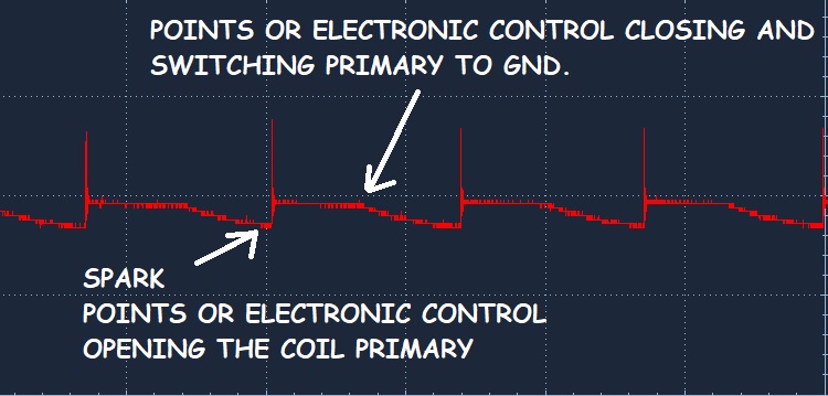
I believe that you are monitoring the ignition noise.
30ms = 1000rpm.
5ms = 6000rpm.
However the noise you measure may not be there when it comes to regular driving as load on the engine will have an effect on the spark energy and hence the magnitude of the cyclic noise that you see.
What happens when you turn on headlights full beam, heater fan, indicators?
Even applying the brake and making the brake lights come on.
The load on the electrical system will have an effect on the noise that you see on the 12V supply.
Worth checking before you make any hardware decisions.
I think Tom has a point, I withdraw my comment in reply #11 as I now realise it is wrong. The alternator / generator will be driven by a belt with unknown ratio to the engine.
I do think your oscilloscope traces are really useful though, lots of people on here making car related projects and not realising how much electrical noise there is in car electrics, good illustration of that.