Measure roll/lean of moving motorcycle

Hi.

I'm trying to make a headlight for my motorcycle that will rotate as bike leans to the side when turning to keep the headlight beam horizontal to the road (so I can see where I'm turning).

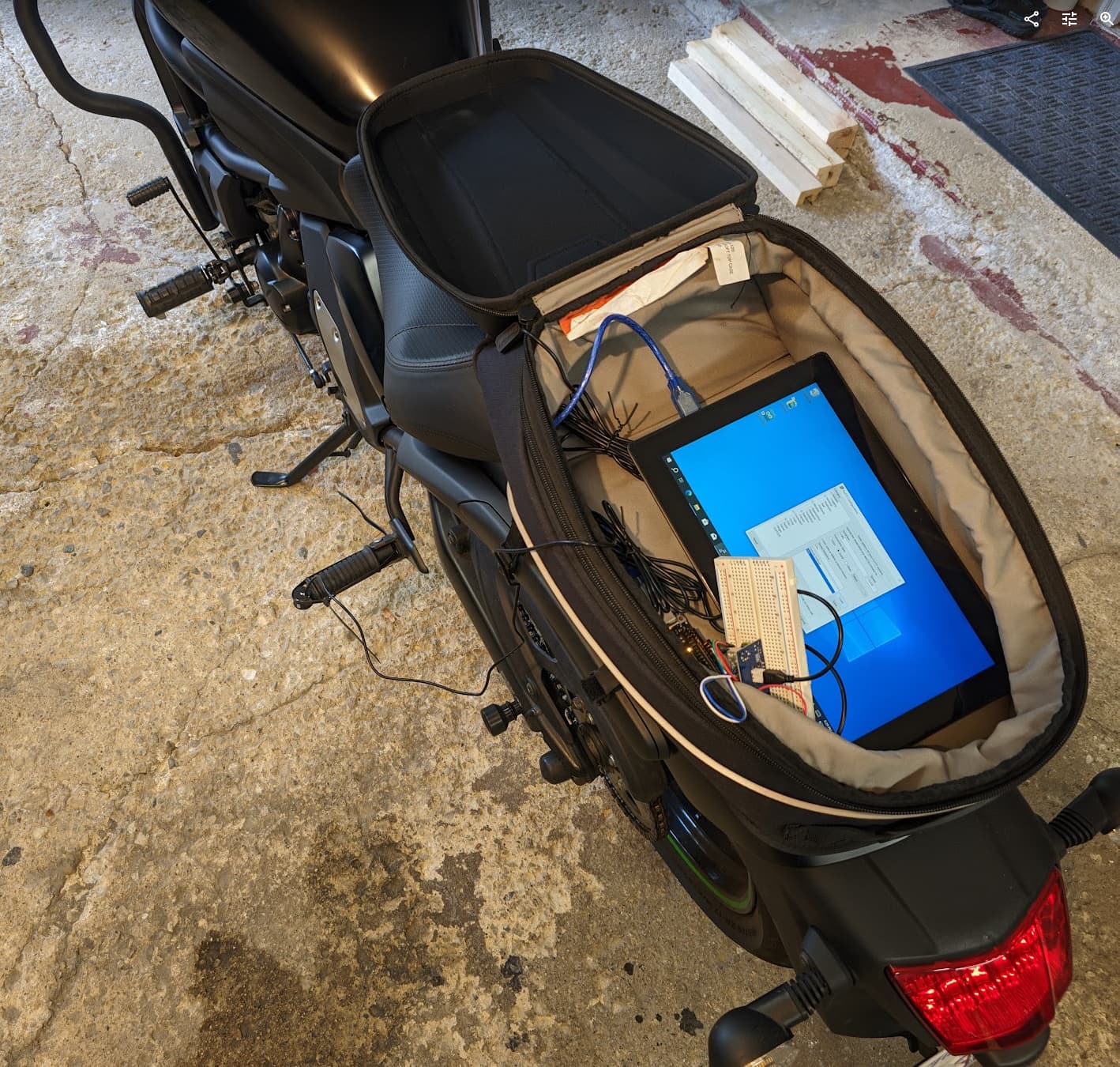
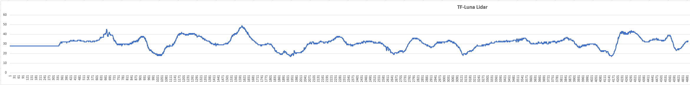
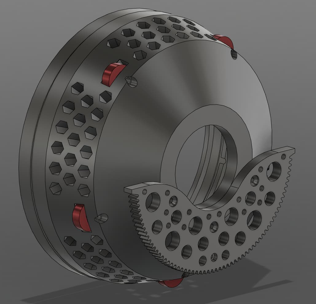
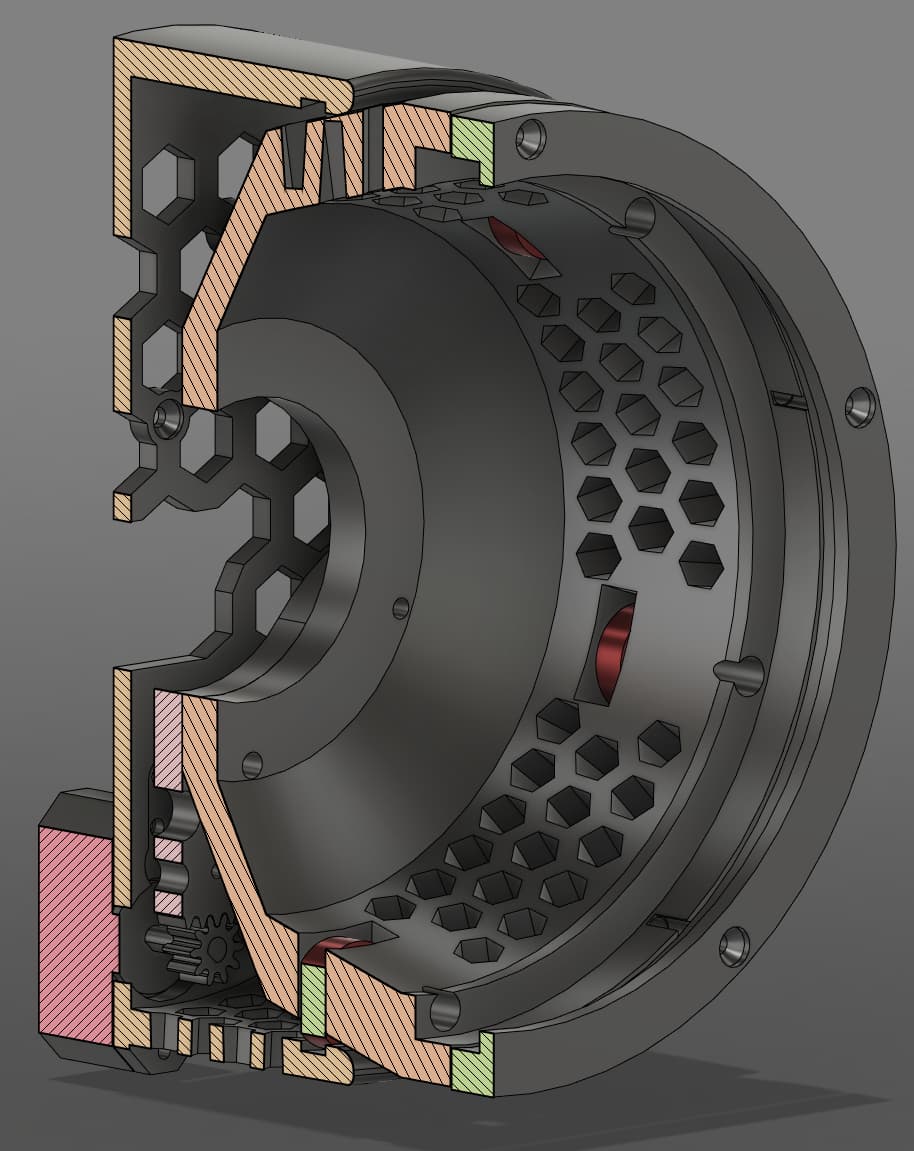
So far I designed the whole thing, 3D printed it, and went on couple test rides, but I'm having trouble with reading the angle/lean/roll of the motorcycle when moving.

First I tried MPU-6050 as I had couple on hand but I couldn't get it to work with the engine running (despite mounting the gyro on the foam or rubber pad far away from the engine). I gave up on that gyro probably too fast but the readings were garbage as soon as bike started.

I tried my luck with BNO055 (Adafruit breakout board) and it was better but sensor was randomly losing calibration and having to stop the bike and rotate sensor around makes the whole project pointless. Sometimes it would shift when going in the straight line for longer period of time and standing still (with engine running) would fix it, but where's fun in having to stop every couple minutes?

I also tried WT901 and so far had best results. But if I lean the bike and accelerate/decelerate during the turn then reported angle doesn't match the actual angle of the bike. If I try to keep the speed relatively constant then it kinda works. Problem with this sensor is that I can't find many projects for reference, just some very basic code that pulls data from the sensor.

So what hardware & software should I use to measure the lean of the motorcycle during movement? At this point I'm ready to throw some money on some badass gyro that will do everything for me.

Please advise.
Thanks.

The BNO055 should work as the sensor fusion can give accurate results for long periods of time. How do you know that you need to calibrate the sensor periodically? The reason you are seeing odd results while acceleration is that both the BNO055 and WT901 use builtin sensor fusion that use the accelerometer to determine orientation in combination with the magnetometers and gyroscopes. There is really no way around that other than using soley the gyroscopes for orientation but they will quickly lose accuracy due to gyro drift. If you want to try however, you can use my library (JRDPropulsion (Aryan Kapoor) · GitHub) to get the true orientation using only the gyroscopes and not the "tilt" angle. This is important as most libraries just give the tilt angle which is not what you want since it assumes that you dont roll.

1 Like

For BNO055, when reading was drifting (like showing 15 degrees when bike was straight), calibration value for accel was dropping to 1 and mag was dropping to 0. That's why I assumed it reported wrong data due to calibration issues. When I stopped for couple seconds then reading often (not always for some reason) returned close to 0, but I don't remember if calibration data changed.

I thought getting angle of the bike would be the simplest part of this project. Oh how wrong I was.

Do you mean the "DCM-Orientation"? Anyways, thanks for the help.

So I dont think you need to worry about the calibration state as you are likely sometimes getting incorrect data due to the accelerometer being used (cant use accelerometer to determine orientation while accelerating) and not the sensors not being calibrated. Yes, I mean the DCM orientation library. You can try to use it and do some ground testing but there is a chance that it might not work too well along long periods of time.

1 Like

Can you also post the original code that you used during testing?

Also, now that i think about it, you should be able to use the angle and probably dont need the "orientation" and the dcm wont make a difference since you only need the lean angle and the sensor moves with the motorcycle. Sorry for sending you on a goose chase. It this case the tilt angle alone should probably do just fine. What I would probably do is stick with the BNO055 as its the best sensor out of the ones you mentioned. Then, I would try to use the raw gyroscopes, intergrate them over time and use that to control the headlight. If your sensor measurements are noisy, like the mpu6050 that you meantioned, you could try some filtering. try searching "simple kalman filter" and feed your angle values there. Dont use the builtin sensor fusion stuff.

I don't mind posting my code, except that it's a mess at this point and it's mostly menus, buttons, and stepper motor. Reading the gyro data from BNO055 or WT901 are like 2-3 lines of code taken from the examples from their respective libraries.

I was using the build-in fusion as I thought it's the magic recipe for the sensor to do all math for me and just report back its position.

I think I tried reading just the gyro data back when I had only MPU6050 and it was so messy even when lying flat on the desk that I thought I can't possibly use it.

Time to go to sleep. I'll try those couple things soon and report back.

People have posted attempts to measure motorcycle lean, and to my knowledge, no one has succeeded with consumer grade IMUs.

For several reasons, sensor fusion is simply not accurate enough to compensate for the centrifugal component of the acceleration, making it impossible to subtract the gravity vector with enough accuracy. This post explains one of the basic problems: Using Accelerometers to Estimate Position and Velocity | CH Robotics

The BNO055 is among the worst of the lot, because the automatic sensor calibration is so poor.

I think you were right the first time. A turn is acceleration, and DOWN will likely match the natural lean angle. All one is going to get out of using an accelerometer for measuring lean angle while in a turn is an indication of unnatural under-lean or over-lean.

As for the gyroscopes, they will drift. If you don't nudge the gyroscope integration towards the accelerometer data it will drift greatly, and if you do it will drift towards the shifting DOWN, following the lean angle.

One might be better off measuring lean by proximity to the road surface and calculating.

1 Like

Hello o0klocek0o

Take a view here to get some ideas.

Have a nice day and enjoy coding in C++.

I've been mostly lazing around and finally decided to give up on gyro/accel approach. I can't make it work and I can't find any other people who made it work.

I decided to give DaveX's idea a try - using some kind of distance measurement to get the lean.

I logged the data from two JSN-SR04T (ultrasonic sensors, look exactly like those in car bumpers) sensors ziptied to passenger's foot pegs.

Here are the graphs of the readings:

The only "filter" used here is that I don't log data if any sensor reads 0 (as it sometimes does that for some reason). Unfortunately I don't have any data from gyro/accel anymore to show and compare but nothing was that nice and that says something. There's no drift! (well duh, since I'm measuring distance to the road surface)

I also got MakerFocus Lidar, the so called "TF-Luna" Amazon link and library taken from budryerson github. There is no filtering of any kind here. Just raw data from the sensor:

I must say that Lidar looks very promising. I ordered second sensor as I need two in order to differentiate between bike leaning and bike height changing due to potholes (or me having too much for lunch). When I get the second Lidar and get around to working on this project I'll post another update.

Edit: oh boy it has been 12 days already? Lidar graph, around 661 mark, is most likely me driving off from the driveway onto the road. Shows that I must have two sensors and take difference between them to calculate the lean.

1 Like

Looks very promising! Keep us posted on your progress. This topic has come up several times before and people will be interested.

It's been a while again, but this time I come with a big update.

Not relevant to the original question, but here's how I made the headlight:


The inner bucket has 5 bearings that ride in the channel in the outer housing. Whole thing is moved by the stepper motor, right now it's a "short body nema" . Currently, gear ratio is 9:1.

That's how the 3D printed headlight looks on the bike. It's one of those LED Jeep headlights from Amazon. I added fog lights as high beam on the main headlight is weak. Fog light are actually too bright but I'm gonna keep them anyways.

There are two MakerFocus TF-Lunas just hot glued to the rear of the bike. One on each side.

To calculate the angle from the distance I just did ("left sensor reading" - "right sensor reading"), then gathered some data with this reading and digital angle gauge. Data is plotted in LoggerPro and I used "best curve fit" to obtain a function used to convert this distance to angle.

Here's a short demo video with headlight on the bike:

I think it looks pretty cool from the 2:40 mark.

Right now I take 10 distance readings and average them out. Speed of the stepper is also turned down to prevent it from skipping steps. In the "inside garage" part you can see that headlight is lagging behind the bike. Also I only gathered data by leaning bike to the left and then simply inputted the same data with negative signs in front for the right. Lunas must be glued unevenly as when leaning right, angle reads too high. I think I'll keep it that way - there's less worry about blinding oncoming traffic if right side is too high.

Whole thing works decent how it is now. There's couple things to fix, including:

  • increase gear ratio/use bigger stepper - I would like the headlight rotation speed to be higher than it is now, but stepper will skip if I increase the speed. Could possibly bump up the current but stepper is getting pretty hot right now.
  • reprint the inner housing - I made some mistakes that were fixed with file/grinder/drill. Gap between bearings and outer bucket was too big so I pressed in some sleeves on the outside, but now the headlight makes this squeaking sound when rotating.
  • waterproof it / tidy up the wiring - or at least give it a fighting chance in the rain. I've never ridden in the rain yet despite having bike for couple of years.
  • buttons, display, and sensors are mostly held together with hot glue, which is a great temporary (holds fine and easy to remove with isopropyl alcohol but might melt if bike left on the sun)
    ...and probably more.

Do you think it's worth sharing the files/code for this project? I would need to fix some things before that tho. What would be the best place?

Anyways, thanks for the help. I would never think of using the distance sensors and I've gotten nowhere with the gyros.

2 Likes

Great job! If you want to post your work, github is convenient and personal accounts are free. There is a learning curve, of course.

Nice! That's working very effectively, and good video too.
Innovative to use the Lidars for distance sensing.
Every motorbike and Arduino enthusiast should be all over this like a rash. Maybe you could make and sell a few for people that dont have the capability.

Credit for idea to use distance sensors goes to DaveX (post #9)

I fixed some of the issues but didn't reprint the whole project yet - it will take couple of days.

Anyways, here are all the files:
https://github.com/peterPacho/Motorcycle_headlight

1 Like

This topic was automatically closed 180 days after the last reply. New replies are no longer allowed.