Dear all.
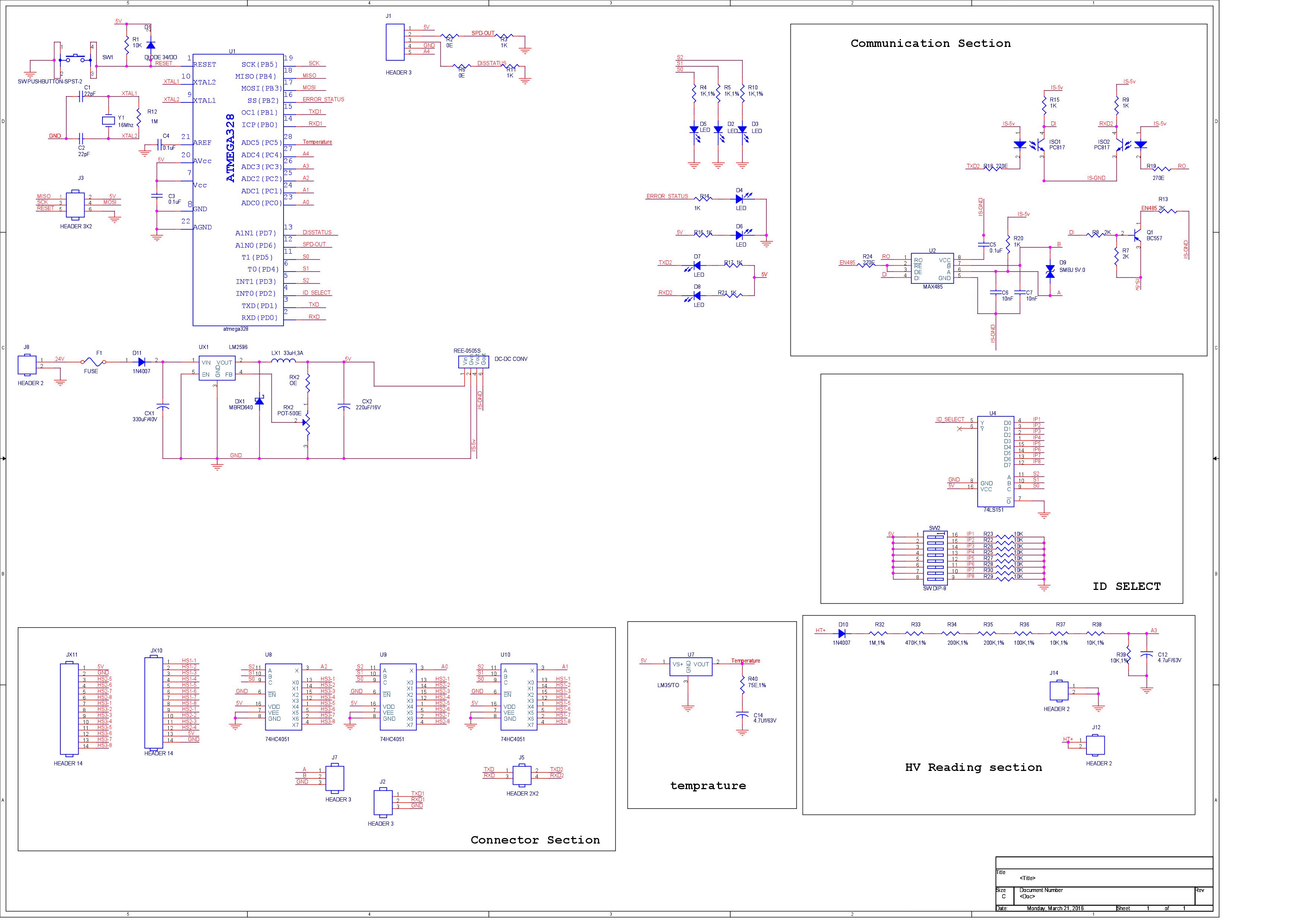
Here i am attaching old and new schematic for reference.While designing the old board i have made mistake keeping HV- (j14) as common ground reference .
J14 and j12 are connected with high voltage 0-700V dc. Using voltage devider network i am dropping to 0-5v output and feeding analog A3 pin.
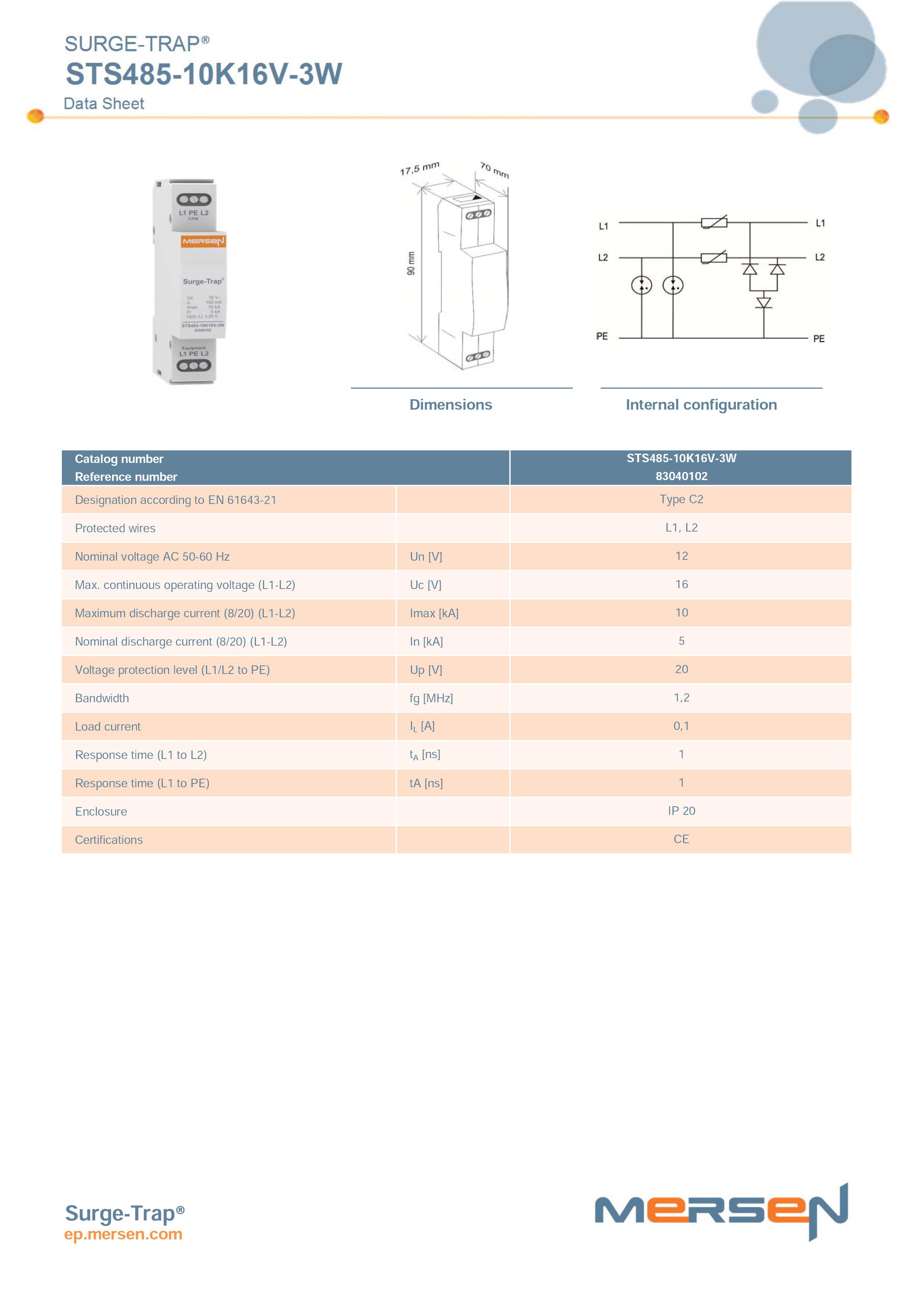
I am taking connection of A&B from (J7 connector ) and connected to A & B of the communication SPD**(data sheet attached)** . and earth of communication connected to ground/earth terminal.
Problem statement:
with communication ground connected , When i measure voltage across the j12 . found voltage around 700V.
with communication ground removed,When i measure voltage across the j12 . found voltage around 5V.also when i removed HV+ & HV- wire it operated normally.
So when i tested out i found due to common ground sharing i found 700V .
My question is
How can i separate J12,J14 , i.e HV - ground seprate.
Method1:
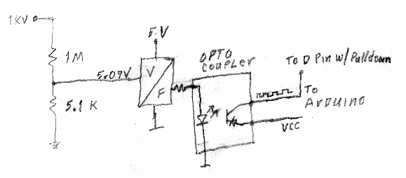
Use Voltage transducer ; LM20-P or RTVSM10/25A.I have made setup like this as shown in Capture.
input voltage 260V DC r1=20Kohm and Rm=150ohm supply voltage + or -15v
With this setup. I am getting smoke at input HVside. Can someone suggest what mistake i have done
Method2:
Refer New schematic, I found when voltage measured across A,B w.r.t HV- or earth plate i am getting 700V. So planned to separate the ground for communication side. SO i used isolated 5vDC to 5vDC out put .
When i try with same setup still problem exist.
If i removed communication earth , boards starts working normally. I also replace with communication SPD from other vendor. Issue remains same.
Can someone suggest me How can i measure High resistance , keeping ground isolated.Like HV- (high voltage ground potential)should be separated from Arduino Ground(or controller ground).