allanhurst:
Well...
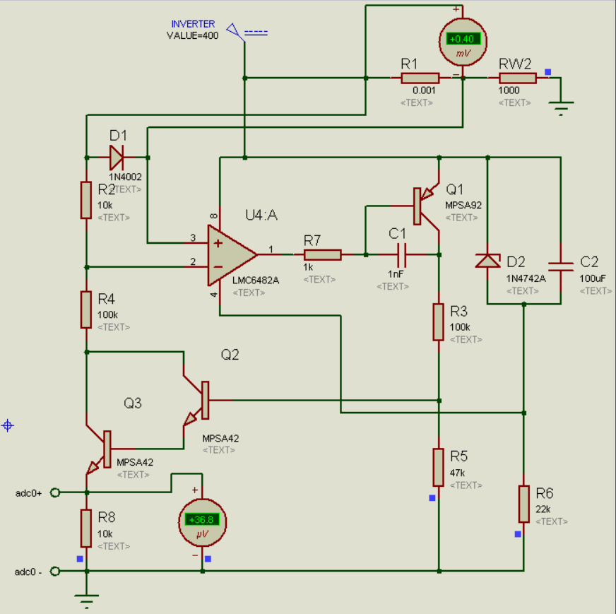
1/ I'd recommend a OPA192 for this - much better Vos. Or maybe an ICL7660 - near zero Vos - but if you want to go that way I'll have to redesign.
2/ re-read my earlier posts and apply the equation - R2 has to be a small value - thought you understood this.
10k gives a very small output. Try 2 ohms
3/ You show an input voltage of 400 - if you do that you'll get magic smoke! Your original requirements only implied 200v max above ground ( your diagram in post #32) . The design is good for 250v or maybe a bit more.
And I do hope your 400v is clean dc and not just rectified 400 vac
- in which case it could go to 400 x sqrt2 or 566v peak ! - please confirm.
4/ You can't power the opamp sitting at ~+200v from 12v on the arduino sitting at ground! Magic smoke big time!
5/ Note your diagram implies a dissipation of up to 160 watts - 400v across about 1k....had you noticed ? are the resistors appropriately rated? where are they ? - they're going to get HOT!
Allan
ps .... who thought this whole thing up? - if you merely want to measure the change of resistance of a bit of foil while being etched , there are much easier ways..... why does it have to sit at 200v above ground and be driven by a split current source dissipating 160 watts? A precision constant current source of a few hundred mA at low voltages is easy-peasy.
If you're a technician given a job by postgrads ( who probably know nothing of electronics) - as I guess - show them these posts, and particularly these comments, and get them to talk to me .
Hello,
1/ OPA192 is really good, but could not find any vendor yet. That's why was simulating using the LMC6482 as it is available. I don't want to put you through too much work as to redesign the circuit. You are already helping a lot and I am really grateful. So please wait till I have some actual tests done.
2/ As posted, changing the R2 have no effect in simulator. (using Proteus). Please check if there is any error that I may have missed something.
3/ Though 220-230 is the typical voltage, the max voltage can go upto 400V and yes DC multi-meter reads 400, hope that means pure DC, right? Environment noises can be present though.
4/ Yes though the diagram do show a high dissipation, but actually it does not. The voltage only gets increased to maintain a good flow of current around 0.05A to 2A at max. The max 2A current will only flow if the total resistance is very low. The supply is generally 200W btw, so it can deliver 160W if load requires.
Also why are we even considering the load? The load could be any high watt load.
EDIT: And the load is on both side of R1, almost equal on both sides. Taking this into account how should I power the OPAMP now? Should I supply it directly from the source like before?
At 2A output the drop across my sense resistor of 0.5 Ohm is 1V only that makes the power at the sense resistor as 2W.
And R1 is the part of current conducting material (eg. wire). Even if R1 is as large as 1k and the current is 0.05A, The max power is 2.5W. Even though in practical cases the R1 will never be 1k, R1 is generally less than 1 Ohm. So I don't think we have to consider much power dissipation, atleast for now.
AND NO I AM NOT GIVEN ANY PROJECT BY GRAD STUDENTS. Though I was a grad student a few years back, and currently a fresher electronics engineer with very low experience. I am trying to make a LAB equipment here to measure resistivity of materials. And NO, the low voltage current source is not going to work here, as a current from the supply is already flowing through the material when we are doing the measurements for R1.
5/ Another question, I know that the diode D1 is protecting the circuit from high voltage due to open R1, or high R1, but how can I calculate the measurement range of the circuit? without trial and error.
Thanks again.