I am trying to measure the time between pulses and RPM from 2 shaft encoders using an Arduino Uno. Both encoders provide 8 pulses per revolution and the shaft rotates between 150-300RPM
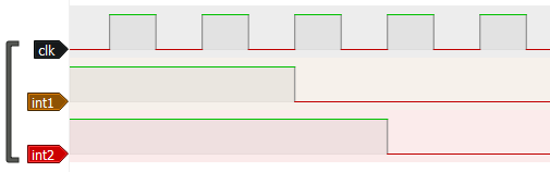
Sensor B can lag behind Sensor A by duration T which can range anywhere from 4 microseconds to 550 micro seconds.
I would like to average results (RPM and T) over 40 pulses or 5 shaft revolutions and also determine the RPM from this by counting either pulses over a time period.
There are no "scripts" in Arduino, only sketches. It would look like a lot of low level processor register configuration, along with interrupt service routines and mainline code to interface with those.
The drawing suggests that you want to measure the time difference between two falling edges, on different pins.
I think that could be done with direct port read (one instruction, 62.5 ns) plus some code to detect the individual edges, which would start and stop Timer1 clocked at 16 MHz.
Or XOR the inputs in hardware and drive the capture register input with that result? Although, this would generate a phase difference signal twice on every cycle.
It should be possible too to connect the inputs to the analog comparator circuit via AIN0 and AIN1 and feed that result to the capture register - eliminating the need for an external XOR.
I've been there before. See there, the part about only 4us resolution... also that invokes code execution delays.
The ask was for minimum 4 us measurement interval. It simply can not be done with polling and micros() for those two reasons.
If you involve interrupts, it will get even slower, unless the interrupt is a response to an input capture. Look at the overhead in an interrupt call/return.
This is one of these threads where the application was not outlined. The first time I read the first post, I immediately thought this might be some kind of PLL, was going to ask if a hardware PLL circuit might be a complete solution.
If nothing else, an XOR would give you a phase comparison that you could LP filter, and maybe don't need a software solution.
But I never asked about the application, because I get so tired of asking things like that...
the actual function call micros() can take 4 to 5 uS to get the current uS. So if an accuracy of 4 uS is required use an ESP32 cycle counter which can give micros with a 12.5nS resolution or picos or nanos.