I have found several topics here but I am not experienced enough to follow along with the solutions.
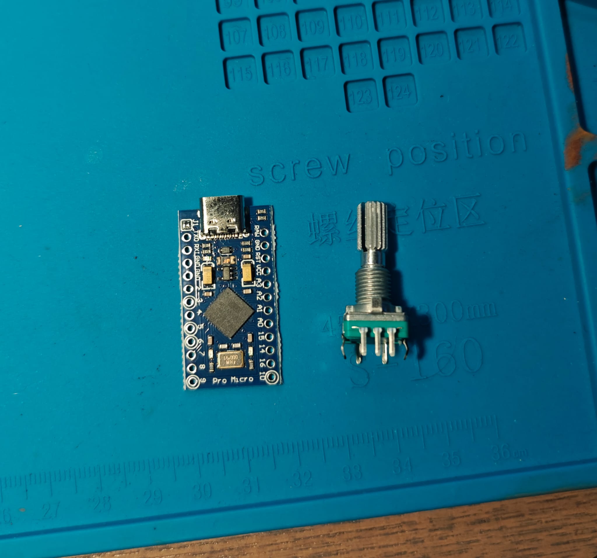
I have micro pro and rotary encoders. I have a flight sim with a helicopter collective that is in desperate need of a throttle addition. I think this is the way to do it. I also have an ESP32 if that is a better option.
Yes it has a push button switch that I do not require for this particular project.
Honestly, I need help with quite a bit. I'd love to know the best way to get this rotary encoder wired to the micro ie where to terminate. And then what the best code would be.
It will be a twist throttle meaning clockwise would increase the helicopters throttle. And anti-clockwise would decrease. Or visa versa
I have used QEI decoder library using interrupt on change to detect changes in the A and B levels on a number of microcontrollers ESP32, Leonardo, ETC - tested with rotary encoders similar to the one in photo in post 1
should work on a pro micro
I have those same rotary encoders as well, I didn't get them to work properly until added 10K pullup resistors to the pins (INPUT_PULLUP from the board turned out to be to weak) and 100nF de-bounce capacitors (Pin to GND)
Then i created this test sketch to run on a Pro-mini using pin change interrupts. Now since it is using direct port manipulation it won't be working on a micro without modification. Actually i probably shouldn't post it but it may be helpful. I will set 1 encoder up with the pullups and the capacitors later and get it to work with the micro. The Pin Change interrupts seem rather different than on a Pro-mini though, so bear with me. You can also do it using the normal interrupt pins on a Micro, that may be easier to accomplish.
The basic idea is that you connect either the A or the B pin to an interrupt pin, and connect the other to a non-interrupt pin, Set the interrupt to 'FALLING' and read the status of the non-interrupt pin, which will tell you the direction the encoder was turned. For this type of encoder that is exactly what you want, but without the 10K pullups & the capacitors, all bets are off.
(example code, far from perfect for you purpose sorry about that.)
#define Y_LED 7
#define ENC1_X 16
#define ENC1_A 3
#define ENC1_B 4
#define ENC2_A 5
#define ENC2_B 6

volatile int8_t dir = 0;
volatile int8_t val = 0;
volatile bool pressed = false;

void setup() {
  pinMode(Y_LED, OUTPUT);
  pinMode(ENC1_A, INPUT);
  pinMode(ENC1_B, INPUT);
  pinMode(ENC1_X, INPUT);
  Serial.begin(115200);
  Serial.println("PCINT test started.");
  PCICR |= B110;
  PCMSK2 |= 1 << 3;
  PCMSK1 |= 1 << 4; //B00010000;  pin A4 PC4
}

void loop() {
  static int8_t oldVal = 0;
  BlinkLed();

  if (oldVal != val) {
    Serial.print("New Value = ");
    Serial.println(val, DEC);
    oldVal = val;
  }
  if (pressed) {
    Serial.println("Button pressed !");
    pressed = false;
  }
}

void BlinkLed() {
  if ((millis() / 500) % 2) {
    digitalWrite(Y_LED, HIGH);
  }
  else {
    digitalWrite(Y_LED, LOW);
  }
}

ISR (PCINT1_vect) {  // for multiple buttons we need to keep track of which button pressed
  static uint32_t lastFired = millis();  // or we can't use press combinations
  if (!pressed) {
    uint8_t in = PINC;
    in = in & 16;
    if ((!in) && (millis() - lastFired > 50)) {
      pressed = true;
    }
  }
  lastFired = millis();
}

ISR (PCINT2_vect) {
  uint8_t in = PIND;
  uint8_t in1 = in & 24;
  if (in1 == 16) {
    val++;
  }
  else if (in1 == 0) {
    val--;
  }
}
Just as an update, dug up an unused micro, grabbed an encoder like the one shown by the OP. (EC11) Added 100nF capacitors between the A / B & GND and added 10K pullups to A & B pins.
Put this on a breadboard, which of course makes it a tad unstable, but when i hold the encoder while i turn it, it's OK. Will make a small testing version later that is soldered.
Wrote this
#define A_PIN 2
#define B_PIN 15

volatile int8_t counter = 0;

void setup() {
  Serial.begin(115200);
  while (!Serial);  // for native usb boards
  Serial.println("Encoder on a Micro");
  pinMode(A_PIN, INPUT);
  pinMode(B_PIN, INPUT);
  attachInterrupt(digitalPinToInterrupt(A_PIN), Count, FALLING);
}

void loop() {
  static int8_t oldCounter = 0;
  int8_t loopCounter = counter;
  if (oldCounter != loopCounter) {
    Serial.print("New Value : ");
    Serial.println(loopCounter, DEC);
    oldCounter = loopCounter;
  }
  delay(1);
}

void Count() {
  if (digitalRead(B_PIN)) {
    counter++;
  }
  else {
    counter--;
  }
}
This uses an 8 bit variable as a counter, so interrupts can remain enabled while reading / copying it.
Only 1 interrupt pin per encoder is used, so with just the external interrupt pins you could use 5 encoders.