Mighty 1284P not happy

Hi everyone,

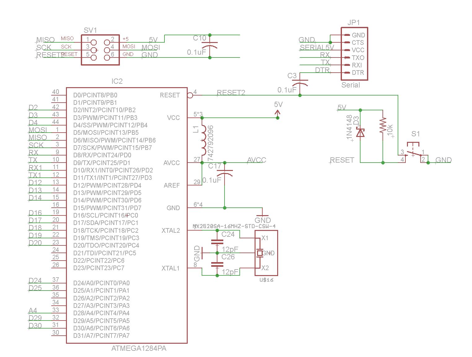
After a bit of a hiatus, I am once again having some fun with a DIY 1284P board. I've followed the paths of the pioneers (i.e. maniac bug and Mr. Crossroads) re: the circuit design with some minor changes. I wonder if I may have been tripped up by said changes, so here first is the error message I got from my MKII AVR ISP when I tried to upload blink tonight:

avrdude: Version 6.0.1, compiled on Jan 15 2015 at 12:42:51
Copyright (c) 2000-2005 Brian Dean, http://www.bdmicro.com/
Copyright (c) 2007-2009 Joerg Wunsch

System wide configuration file is "/Applications/Arduino.app/Contents/Resources/Java/hardware/tools/avr/etc/avrdude.conf"
User configuration file is "/Users/CvW/.avrduderc"
User configuration file does not exist or is not a regular file, skipping

Using Port : usb
Using Programmer : stk500v2
avrdude: usbdev_open(): Found AVRISP mkII, serno: 000200074270
AVR Part : ATmega1284P
Chip Erase delay : 55000 us
PAGEL : PD7
BS2 : PA0
RESET disposition : dedicated
RETRY pulse : SCK
serial program mode : yes
parallel program mode : yes
Timeout : 200
StabDelay : 100
CmdexeDelay : 25
SyncLoops : 32
ByteDelay : 0
PollIndex : 3
PollValue : 0x53
Memory Detail :

Block Poll Page Polled
Memory Type Mode Delay Size Indx Paged Size Size #Pages MinW MaxW ReadBack


eeprom 65 10 128 0 no 4096 8 0 9000 9000 0xff 0xff
flash 65 10 256 0 yes 131072 256 512 4500 4500 0xff 0xff
lock 0 0 0 0 no 1 0 0 9000 9000 0x00 0x00
lfuse 0 0 0 0 no 1 0 0 9000 9000 0x00 0x00
hfuse 0 0 0 0 no 1 0 0 9000 9000 0x00 0x00
efuse 0 0 0 0 no 1 0 0 9000 9000 0x00 0x00
signature 0 0 0 0 no 3 0 0 0 0 0x00 0x00
calibration 0 0 0 0 no 1 0 0 0 0 0x00 0x00

Programmer Type : STK500V2
Description : Atmel STK500 Version 2.x firmware
Programmer Model: AVRISP mkII
avrdude: stk500v2_recv_mk2: error in USB receive
Hardware Version: 2
Firmware Version Master : 1.10
Vtarget : 4.9 V
SCK period : 8.00 us

avrdude: stk500v2_command(): command failed
avrdude: stk500v2_program_enable(): bad AVRISPmkII connection status: Unknown status 0x00
avrdude: initialization failed, rc=-1
Double check connections and try again, or use -F to override
this check.

avrdude done. Thank you.

Error while burning bootloader.

My question to the experts: Does the above suggest that the board is alive or may I have cooked the MCU in the reflow oven?

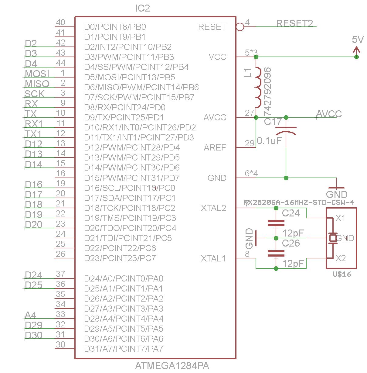
Now for the changes I made that may also be the cause of the above unhappiness: Instead of the resonators I have used in the past, I switched to a crystal: CS05116-16M NDK America, Inc. | Crystals, Oscillators, Resonators | DigiKey

Unfortunately, I managed to order the wrong version of the crystal - the 12pF load capacitance version instead of the 8pF model I intended to order. Thus, my calculated 12pF external capacitors are obviously wrong and need to be replaced. Would 20-22pF caps look like a better bet?

FWIW, I am running Arduino 1.6.1 on a OSX 10.10 machine. I downloaded the mighty library for version 1.6 from github... Many thanks to all again, this is an amazing forum and community.

Are fuses set to use external crystal as clock source? If yes, was that process performed successfully after assembling the board?

If yes to both, your crystal isn't doing it's thing - fix it and the chip will work.

Otherwise, suspect solder bridges or board design errors. My general process is - Check all isp pins and crystal pins for shorts to each other, power, and ground. Make sure power and ground aren't shorted, and check that each isp pin really does go to the right pin. Check with an ohm meter so you can find bad solder joints. Is reset at vcc when powered?Rework as needed. Did you put the isp header on the wrong side if the board?

I really appreciate the help. Here is the schematic:

Here is the board showing the relevant connections. Note: the 1284P is on the TOP side, the ISP header is on the BOTTOM side. The header pins appear to be correct (i.e. MOSI to MOSI, and so on). I feel pretty confident that the connections are correct as I have used this ISP header many times while programming past 1284Ps and 328Ps.

At the bottom of that image, you can see the serial header with the DTR pin to the left. A track winds its way up to the RESET pin on the 1284P, with a 0.1uF cap bridging over one of the 5V lines to make the connection.

At the bottom of the picture and to the left, a 10k resistor pulling up Reset ties into the 5V supply. 5V from Serial snakes its way down from the serial header and dumps its power via a Schottky diode (this is how the board is powered during programming. In the past, I had no issues with this setup, i.e. Serial powering a board while the ISP burns the bootloader).

I checked for solder bridges and so far, I find none. I have attached a iPhone pic so you can see how the solder is distributed. For what it's worth, I used a stencil and a reflow oven.

As for the fuses, I am confused, I thought using the AVR MKII ISP and 'burn the bootloader' would do this? Or is there an additional step I missed after attaching a virgin 1284P to this board?

I checked all the pins for the ISP header.
ISP GND to another GND Pad on board is 0.1 Ohms.
ISP GND to the ISP 5V = 290kOhm
ISP GND to ISP RESET = OL
ISP GND to ISP SCK = 340kOhm
ISP GND to ISP MISO = 340kOhm
ISP GND to ISP MOSI = 320kOhm
ISP 5V to the other pins on the header are similar, except for ISP 5V to ISP RESET, which is 10k (as expected)
ISP SCK to MOSI, MISO is 860kOhm

The two crystal lines to each other are 860kOhm
ISP MOSI, MISO, and SCK to their respective pins on the 1284P are 0.2Ohms.

Board voltage is 4.9V (Serial line via Schottky Diode), ditto for ISP 5V to ISP GND.
ISP Reset is 4.9V

I presume all is left is the caps on the crystal?

Can you Attach your pics? I can't open postimg.org site.

Does the MKii have green light when you plug it on before you start programming?
avrdude: stk500v2_program_enable(): bad AVRISPmkII connection status: Unknown status 0x00
That looks like poor connection, or perhaps pins swapped.

Hi Crossroads, and thanks for replying. How does one attach images? I thought the forum here didn't allow image uploads, just links. As for the MKII, yes its light goes from red to green when I insert the 6 pin polarized header into the polarized receptacle. Suggests to me that the pin assignments may be correct.

To Attach: Reply, then scroll down a little and click Attachments and other options.

Could also buzz out that the pins as the MKii sees them go to the right 1284 pins:
MISO 1 2 VCC
SCK 3 4 MOSI
Reset 5 6 Gnd

TQFP pins
MOSI - 1
MISO - 2
SCK - 3
Reset - 4
VCC - 5, 17, 38, and 27 if AVCC tied to VCC
GND - 6, 18, 28, 39
Can also work around the TQFP in pairs, make sure no pins are shorted to each other:
1-2, 2-3, 3-4, 4-5, etc.

FWIW, I just cleaned the board (saw some solder flux) and the results are similar, i.e. no go.

Thank you, Crossroads! Images are attached below.

Here is an image with the relevant headers and the MCU. Pretty standard stuff, I think.

Electrically, RESET and RESET2 are joined via the tactile switch. I confirmed the electrical continuity

Also 'walked' around the 1284P with a DMM and found no adjacent pins with less than 4.7k resistance between them, which makes sense since a number of the pins go to 4.7k pullup resistors. No outright shorts other than when the probes touched... AVCC, VCC, and so on are all at 4.9V, as expected. Power indicating LED is lit.

I also checked the electrical continuity from the ISP header to to three pins on the chip. All seems well there. Presumably, the MKII would not light up green if the polarity on the header was wrong?

Constantin:
As for the fuses, I am confused, I thought using the AVR MKII ISP and 'burn the bootloader' would do this? Or is there an additional step I missed after attaching a virgin 1284P to this board?

Yes, fuses are set when you do 'burn bootloader'

Did you do this step after assembling the board?
Was it successful? Or did it immediately error?
I suppose you don't have the output log from that attempt?

If you were able to write the low fuse successfully, and subsequently, no attempts to program worked, that would tell you with virtual certainty that the problem was the crystal (or user error w/regards to what you set the low fuse to - you'd see the same if you set the clock source to something other than what you intended, either external clock rather than crystal, or an internal clock that's so slow the ISP can't communicate with it)

Hi Dr. Azzy,

I'm not sure I tried burning the bootloader first, and unfortunately, that output was not saved. However, none of the attempts to burn a program or bootloader were successful. I tried uploading blink first, I think.

How does one tell the fuse configuration? Can they be reset later on?

Schematic & images look ok.
Has the board been bootloaded using the IDE before?
Are you using Full Swing Crystal Oscillator (low fuse byte ends in 7?)

Burn bootloader can be done at any time.

Fuses can be seen in boards.txt

No, I have failed at every attempt to burn the bootloader or a program. Here is the latest sample output:

avrdude: Version 6.0.1, compiled on Jan 15 2015 at 12:42:51
Copyright (c) 2000-2005 Brian Dean, http://www.bdmicro.com/
Copyright (c) 2007-2009 Joerg Wunsch

System wide configuration file is "/Applications/Arduino.app/Contents/Resources/Java/hardware/tools/avr/etc/avrdude.conf"
User configuration file is "/Users/CvW/.avrduderc"
User configuration file does not exist or is not a regular file, skipping

Using Port : usb
Using Programmer : stk500v2
avrdude: usbdev_open(): Found AVRISP mkII, serno: 000200074270
AVR Part : ATmega1284P
Chip Erase delay : 55000 us
PAGEL : PD7
BS2 : PA0
RESET disposition : dedicated
RETRY pulse : SCK
serial program mode : yes
parallel program mode : yes
Timeout : 200
StabDelay : 100
CmdexeDelay : 25
SyncLoops : 32
ByteDelay : 0
PollIndex : 3
PollValue : 0x53
Memory Detail :

Block Poll Page Polled
Memory Type Mode Delay Size Indx Paged Size Size #Pages MinW MaxW ReadBack


eeprom 65 10 128 0 no 4096 8 0 9000 9000 0xff 0xff
flash 65 10 256 0 yes 131072 256 512 4500 4500 0xff 0xff
lock 0 0 0 0 no 1 0 0 9000 9000 0x00 0x00
lfuse 0 0 0 0 no 1 0 0 9000 9000 0x00 0x00
hfuse 0 0 0 0 no 1 0 0 9000 9000 0x00 0x00
efuse 0 0 0 0 no 1 0 0 9000 9000 0x00 0x00
signature 0 0 0 0 no 3 0 0 0 0 0x00 0x00
calibration 0 0 0 0 no 1 0 0 0 0 0x00 0x00

Programmer Type : STK500V2
Description : Atmel STK500 Version 2.x firmware
Programmer Model: AVRISP mkII
avrdude: stk500v2_recv_mk2: error in USB receive
Hardware Version: 2
Firmware Version Master : 1.10
Vtarget : 4.9 V
SCK period : 8.00 us

avrdude: stk500v2_command(): command failed
avrdude: stk500v2_program_enable(): bad AVRISPmkII connection status: Unknown status 0x00
avrdude: initialization failed, rc=-1
Double check connections and try again, or use -F to override
this check.

avrdude done. Thank you.

Error while burning bootloader.

Is that the same board or a new one?

The "smoking gun" I describe, thinking about it more, would only be visible in the first attempt - but that attempt would still fail - because it sets the fuses, and then does a second programming operation to set the lock bits, it would just fail later in the process than on subsequent attempts.

I have no idea what that failure (wrong clock source) looks like for that fancypants ISP you're using. I know what to expect when using a USBAsp or ArduinoAsISP (it reads signature as 0x000000), but with that, I can't tell if that's just what AVRISPmkII gives you in that circumstance, or whether it's failing for a different reasons...

If you use USBAsp/ArduinoAsISP, and it reported something other than signature reading 0x000000, that would suggest that there's a different problem.

I really do think it's the crystal though. There's a version of the ArduinoAsISP sketch that outputs an 8mhz clock on one of the pins - you can use that to revive ones that you've put the wrong clock setting on.

Have you checked that none of the crystal pins are shorted to ground (or eachother)? My most frequent assembly problem on a stencil/reflow board is shorts underneath capacitors.

Check the connections at the 2x3 header end of the cable. I recently had a bout of frustration bootloading via 2x3 header with 328P boards an ended using my press on adapter from hobbyking.com

At the last board after replacing the chip a couple of times, finally realized the ribbon cable was making poor contact (after 4 years of use). Cut it off and crimped on a new connector, problem solved.
http://www.mouser.com/ProductDetail/FCI/71600-006LF/?qs=sGAEpiMZZMs%252bGHln7q6pm24n0txessAMv97Wpyh9hZc%3D
I had bought a tube of them to make cables for the standalone programmer cards so I had one handy.

Crossroads, how do I buy you a beverage of your choice?

Straightened the ISP cable and all of a sudden, the thing burns the bootloader. Next, tried uploading blink and all is well. I would never have thought of that. Thank you!!!

I only stumbled upon it the same way - bent just right, it worked, and it happened to be bent just right when used with the SMD adapter, but not plugged onto a 2x3 header. Struggled with 19 boards before I realized it. Glad you got it working.

Paypal me a couple bucks, I'll get myself a beer after hockey tonight 8)
If you're careful, you might be able to release the header and re-squeeze it a little farther up the cable. I just cut the cable and crimped a new one on.

Hi Crossroads, sent you a PM.

Chiming in. I recently had a failure on a zif socket. The atmega328 only requires a few pins for programming and it happened that the two loose pins on the socket are the crystal pins. Tried and failed several times to bootload and eventually found out it was the zif. Replaced and been happy. Same thing, metal fatigue from several years of use. Probably went through 300 chips though.