Hello. I'm powering a mini breadboard using a battery...but I'm not sure when the power rails are....can you please tell me where I should put the GND and VCC in?
As shown by the red lines in the image below, each row of holes on either side of the slot in the middle of the breadboard have electrical connection with each other (and not to any other row, including those across the central slot):
Each row has the electrical connection, I just didn't feel like drawing a zillion lines.
engineer123498:
but I'm not sure when the power rails are....can you please tell me where I should put the GND and VCC in?
You can use any row you like as rails (just don't use one row for both rails!).
engineer123498:
(Do the parts that stick out on the side have anything to do with the placement of power rails?)
No. The only purpose of those is to allow you to interlock multiple breadboards together (but only in a mechanical manner, not electrical).
Small breadboards with VCC and GND rails have a red stripe next to the holes for power and a blue stripe for ground holes but those are only to help you know that there are two rails. Some boards split the rails, check continuity/never assume you have it!
engineer123498:
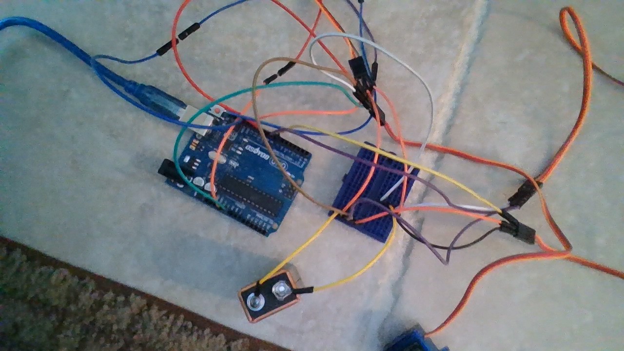
Thanks...but Im trying to use a mini breaboard to power 4 servos with one 9v battery...and it isn't working....(It worked with a regular breadboard)
Here is a picture: file:///C:/Users/lukea/Pictures/Camera%20Roll/WIN_20200329_09_03_29_Pro.jpg
Hi, sorry the C:/ etc will not work.
Please read the post at the start of any forum , entitled "How to use this Forum".
OR http://forum.arduino.cc/index.php/topic,148850.0.html.
It will show you how to attach and then put in your post the image.
Tom...
Servos and PP3 smoke detector batteries - bad idea. Servos and breadboards - bad idea. Servos and both - very bad idea.
I have no idea what you're calling bottom/top or side/side but if you're still not sure which holes connect together just use your DMM on resistance mode and test them. It's not rocket science.
A pretty useless picture, but it confirms that you are using a PP3 battery which cannot provide enough current for very long, particularly when you short it out
Ninety nine percent or more of servo issues we see here are caused by insufficient power. Yours is no different. Get rid of the PP3 and replace it with double As configured to give you 6V.
engineer123498:
If I use the 9v battery....then the servos spin randomly out of my control...and this exact project worked on a regular breadboard.
Exact project...so the same servos, same battery, same wires etc? If so then basically you're saying you got lucky once but now you've run out of luck.
Maybe the servos don't work now because they are not supposed to run on 9V so you've broken them.
Ok...also when I plug the servos in...they 'come to life'. Do they only do this once they are connected to the battery and the yellow wire is connected to a pin on a powered arduino.
