I have a MKR Zero connected to an AD5592 over the SPI interface. I have a small program to write data to one registare and read the data back. This works correctly on a Nano, Nano Every and a Nano 33 BLE. However it does not work on the MKR Zero. The MKR appears to send two additional bytes instead on reading two bytes.
I am running the 1.8.13 IDE and have installed the SAMD Boards (32-bit ARM Cortex-M0+ ) version 1.8.9.
#include <SPI.h>

int ledState = LOW;
const byte chip_select = 4;
const unsigned long Spi_Hz  = 16000000;

const uint8_t DAC_data                  = 0x80;
const uint8_t DAC0_address              = 0x00;
const byte DAC_readback_Register      = 0x01;
const unsigned int Enable_DAC_readback      = 0x0018;


void my_delay(unsigned long millis_delay ) {
  unsigned long start_millisec = millis();
  unsigned long current_millisec = millis();
  while ( start_millisec + millis_delay > current_millisec ) {
    current_millisec = millis();
  }
}

void select_board( uint8_t address, bool state )
{
  unsigned char mask = ( 1 << address );
  if ( state == true ) {
    digitalWrite(address, LOW) ;
  } else {
    digitalWrite(address, HIGH);
  }
}

unsigned int read_board(  uint8_t address, unsigned int thisRegister) {
  byte inByte = 0;           // incoming byte from the SPI
  unsigned int result = 0;   // result to return
  uint8_t msb = ( thisRegister >> 8 ) & 0xFF;
  uint8_t lsb = ( thisRegister & 0xFF);
  SPI.beginTransaction(SPISettings(Spi_Hz, MSBFIRST, SPI_MODE1));
  select_board( address, true );

  // send the device the register you want to read:
  SPI.transfer( msb );
  SPI.transfer( lsb );

  select_board( address, false );
  select_board( address, true );

  // send a value of 0 to read byte at a time
  msb = SPI.transfer(0x00);
  lsb = SPI.transfer(0x00);
  select_board( address, false );
  SPI.endTransaction();

  result = msb << 8;
  result |= lsb;
  return (result & 0xFFFF);
}

void write_board( uint8_t address, uint8_t msb,  uint8_t lsb ) {
  SPI.beginTransaction(SPISettings( Spi_Hz, MSBFIRST, SPI_MODE1));
  select_board( address, true );
  SPI.transfer(  uint8_t( msb) );
  SPI.transfer(  uint8_t( lsb ) );
  select_board( address, false );
  SPI.endTransaction();
}

//  send data for DAC
void set_DAC_data(uint8_t chip_sel,uint8_t dac_num,  unsigned int value)
{
  uint8_t lsb = value & 0xFFF;
  uint8_t msb = DAC_data | ( ( DAC0_address | dac_num ) << 4 ) |  ( (value >> 8 ) & 0x0f );
  write_board( chip_sel, msb, lsb );
}

unsigned int read_DAC_data(uint8_t chip_sel,uint8_t dac_num )
{
  uint8_t DAC_read = 0x80;
  return read_board( chip_sel, ( DAC_readback_Register << 11 )| Enable_DAC_readback | dac_num );
}

void setup() {
  Serial.begin(115200);
  while ( !Serial ) {
    delay(1);
  }
  SPI.begin();
  pinMode(chip_select, OUTPUT);
}

unsigned int dac_data = 0;
unsigned int dac_val = 0;

void loop() {
   dac_data += 1;
   set_DAC_data( chip_select, 0, dac_data );
   dac_val = read_DAC_data( chip_select, 0 );
   dac_data &= 0x0FFF;

   Serial.print( "Dac Data::0x" );
   Serial.print( dac_data, HEX );
   Serial.print( " Value::0x" );
   Serial.println( dac_val & 0xFFF, HEX );
   my_delay(10);

}
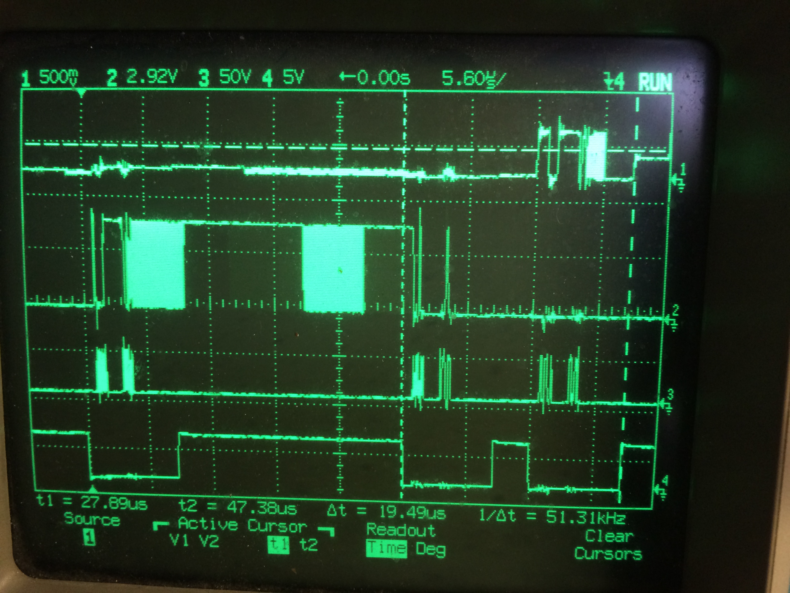
I have two pictures from my 4 channel scope, the first picture shows the trace of the program when runnimng on the Nano, teh second is from the MKR Zero showing the two additional bytes sent instead of reading data from the chip. I assume because the MRK Zero was transmitting the AD5592 chip did not send the data.
The Traces are row1, MISO, row2 MOSI, row 3 SCK and row 4 the chip enable signal.
Hi Pylon
the clock speed was 12MHz, I have tried 8MHz and 4MHz the signals are still the same though longer in time. The two bold lines are correct trace and is due to the scope averaging the waveform. As the lower byte is changing by 1 bit most times, scope shows all scans as one.
At the slower speeds, it can be seen that the zero zero data sent is in the second two bytes the first two bytes are not zero and appear to be 0x08 and 0x18 for some reason
The third set of bytes sent are the zero zero sent in the software, which should be sent in the second block. For some reason the second block contains the two bytes 0x08 and 0x18 and zero zero are sent in the third block. The third two bytes should not be sent the MOSI should be set to inactive so that the MISO can transmit the data back to the SPI master, similar to the first scope display
The third block doesn't look like zeros are sent. I don't want you to interpret your code but scale the scope display to see what is actually transferred over the wire.
Hi attached, another image from scope showing that the third set of bytes are zero zero the clock speed has been slowed to 4Mhz and I have stopped the scope averaging. I had altered the bytes sent ( which are the third set) so that they matched the second set of bytes. That was how I identified hat the second set of bytes were 0x08 and 0x18 and the fact that the bytes I sent were the third set. Scope shows results when I set the Bytes sent to zero zero
The third block is definitely not two zero bytes. But the scope output isn't clear enough to see what value is sent. Is that a storage scope so you can have a bigger scale and move around in the picture? Using that scale you don't see what's transferred but you can tell that it's not 0x00 and not 0xff.
Why do you think it is not zero as the MOSI line is low for the length of the 8 clock pulses and does not go high, like the second pair of bytes
If the third block is all zero bits, then the first must be the same, at least that's my interpretation of that picture but it's definitely no clear enough to tell from what I see.
How long are your bus wires? As the MKR runs on 3.3V longer wires result in a higher capacitance so the signal might no be clear enough at the device end. I'm still a bit surprised that MOSI idles high for the MKR.
I think you have identified the issue the line MOSI returns high after sending data preventing the chip from sending the reply. As this code works correctly on the Nano Every, Nano and Nano 33 BLE it must be in the library for the MKR Zero. Not sure how to tackle that.
Do you have the chip connected directly to the MKR? I almost cannot believe that the MKR hardware is doing this. It looks more like a wrong level converter.
The signals are monitored on the MKRZero pins on the arduino board, the only signal coming onto the board is MISO line which is known to be correct asthe hardware and arduino softwareworks with the Nano board
Got there in the end, the transmission of the Zero bytes, by the MKR are unimportant to the transfere of data. The important part is that the MISO goes high when the chip select is selected for reading(first picture top channel).
For the MKR board the scope was on the input pin to the MKR board and not the chip. had I done this then I would have seen that the wire was broke between the boards. New wire and all fixed. thanks for your help python