I am trying to replicate the circuit and programming here;
with some (I thought) minor alterations as follows;
- I want to use a two-position illuminated latching switch I have, not a momentary one (first attachment). The right hand contact pair are just for the LED. Working left from there each pai of contacts is Switch one, common and switch two.
I have confirmed with a multimeter that when the switch is "up" or "off, there is continuity between Common and S1, and in the "down" or "on" position, connection between S2 and Common. The pairs are completely separate and no position of the button generates continuity between them "across" the switch. , so it's effectove;y two identical switches operated as a single button.
I'm using just the UPper line of contacts in the image.
- Rather than just turning the LED off, I have some WS2812 LEDS attached to the power rail of the bread board. I would like each press of the button to change the colour in the following sequence; Red, Green, Blue, White and then start over back at red again/
I simply can't get it to work and I don't know if it's code or layout related.
I know I have to compensate for the fact that this is a latched switch; it could be in either of two positions at start. Also I can't just check for a "HIGH" from it because it's default status might be high OR low, unlike a momentary...what I need to check is for a CHANGE from LOW to HIGH and back again.
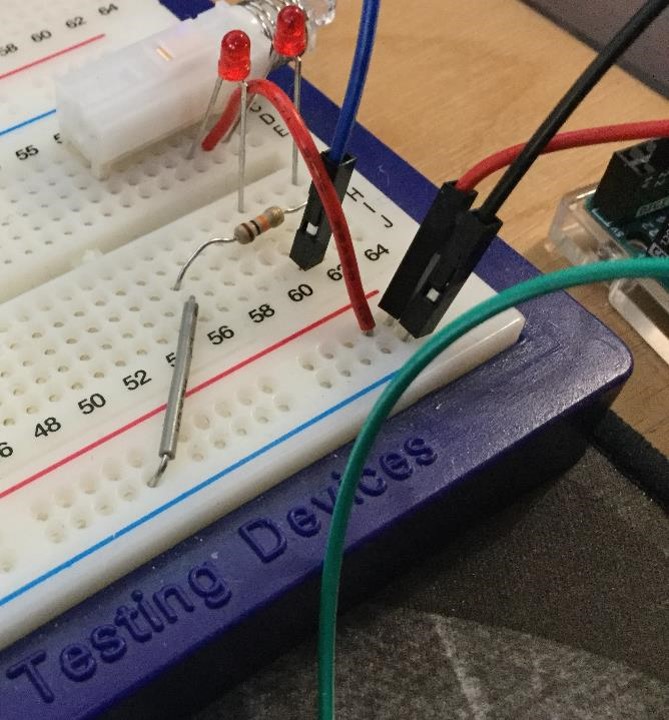
Wiring also slightly different..I've tried to lay it out as close to the sketch as possible, confirmed that it really is a 10K resistor and I added the LEDs just to "see" where the current was going.
Attachments two and three are my bread board and Arduino; the WS2812b's are connected to the power lines you can see on the left of the screen., and a data cable runs to pin 8.
First question - have I misseed sometyhing in the wiring?
Here's my attempt at a sketch;
//Lightsswitch
//Cycles LED colours.
//For testing

#include <Adafruit_NeoPixel.h>

#define N_LEDS           144   //LEDS in strip
#define PIN               8   //output pin 1
const int buttonPin = 22;     // the number of the pushbutton pin
const int ledPin =  13;      // the number of the LED pin
int buttonState = 0;         // variable for reading the pushbutton status
int ColourCode = 1;          // Colour Variable

// Following array allows addressing of pixels by XY position rather than sequential pixel number

int pixelarray[12][12] = {
    {   0,   0,   1,   2,   3,   4,   5,   6,   7,   8,   9,  10,},
    {  22,  21,  20,  19,  18,  17,  16,  15,  14,  13,  12,  11,},
    {  23,  24,  25,  26,  27,  28,  29,  30,  31,  32,  33,  34,},
    {  46,  45,  44,  43,  42,  41,  40,  39,  38,  37,  36,  35,},
    {  47,  48,  49,  50,  51,  52,  53,  54,  55,  56,  57,  58,},
    {  70,  69,  68,  67,  66,  65,  64,  63,  62,  61,  60,  59,},
    {  71,  72,  73,  74,  75,  76,  77,  78,  79,  80,  81,  82,},
    {  94,  93,  92,  91,  90,  89,  88,  87,  86,  85,  84,  83,},
    {  95,  96,  97,  98,  99, 100, 101, 102, 103, 104, 105, 106,},
    { 118, 117, 116, 115, 114, 113, 112, 111, 110, 109, 108, 107,},
    { 119, 120, 121, 122, 123, 124, 125, 126, 127, 128, 129, 130,},
    { 142, 141, 140, 139, 138, 137, 136, 135, 134, 133, 132, 131,}
};
int lightpitch = 1;
int RVa = 255;
int GVa = 255;
int BVa = 255;
int p;                      //pixel number
int x;                      //x-pos in array
int y;                      //y=pos in array
int i;                      //for loops
int n;                      //for loops
int OriginalState;

Adafruit_NeoPixel strip = Adafruit_NeoPixel(N_LEDS, PIN, NEO_GRB + NEO_KHZ800);

void setup() {
  int p;
  // initialize the LED pin as an output:
  pinMode(ledPin, OUTPUT);
  // initialize the pushbutton pin as an input:
  pinMode(buttonPin, INPUT);

  Serial.begin(9600);
  strip.setBrightness(50);
  strip.begin();

  // Test pixels

  strip.setPixelColor (0, 0, 50, 0);
  strip.setPixelColor (10, 0, 50, 0);
  strip.setPixelColor (131, 0, 50, 0);
  strip.setPixelColor (142, 0, 50, 0);
  strip.show();
  delay(200);
  // clear all pixels
  for (p = 0; p <= (N_LEDS - 1); p++) {
    strip.setPixelColor(p, 0, 0, 0);
  }
  strip.show();
  OriginalState = digitalRead(buttonPin); //record position of Switch at start. On=HIGH, Off = LOW
}
void loop() {

  //Following loop sets LEDpin to match Originalstate - use as indicator in addition to LED matrix
  if (OriginalState == HIGH) {
    digitalWrite (ledPin, HIGH);
  }
  else
  {
    digitalWrite(ledPin, LOW);
  }

  Serial.print ("Initialised as ");
  Serial.println (OriginalState);
  delay(250);

  //Turn the LEDs on using currentColourCode
  //Colour
  switch (ColourCode) { //sets channel values to current ColourCode
    case 1:
      RVa = 255;
      GVa = 0;
      BVa = 0;
      Serial.println("Red");
      break;
    case 2:
      RVa = 0;
      GVa = 255;
      BVa = 0;
      Serial.println("Green");
      break;
    case 3:
      RVa = 0;
      GVa = 0;
      BVa = 255;
      Serial.println("Blue");
      break;
    case 4:
      RVa = 100;
      GVa = 100;
      BVa = 100;
      Serial.println("White");
      break;
    case 5:
      RVa = 0;
      GVa = 0;
      BVa = 0;
      Serial.println("Off");
    default:
      RVa = 0;
      GVa = 0;
      BVa = 0;
      Serial.println("Off");
  }


//Loop through X rows of y pixels and set current colour.

  for (x = 0; x <= 11; x = x + lightpitch) {
    for (y = 0; y <= 11; y = y + lightpitch) {
      strip.setPixelColor(pixelarray[x][y], RVa, GVa, BVa);
    }
  }
  strip.show();


  //Next loop basically just waits for a button press, comparing current button State to OriginalState
  do {
    buttonState = digitalRead(buttonPin);  // Value if pressed may be constant "HIGH" or "LOW":
  }
  while (buttonState == OriginalState);   // checks to see if buttonState is different to OriginalState (indicates button pressed)

  Serial.print ("Change detected, moving to next colour. OriginalState = ");
  Serial.print (OriginalState);
  Serial.print (", buttonState =");
  Serial.println(buttonState);


  //cycle colours one place
  ColourCode = ColourCode + 1;                        //Changes colour code
  if (ColourCode >= 6) {                              //Reports start of a new loop. Cycle is R > G > B > W > Off
    Serial.println ("New Loop, back to red");
    ColourCode = 1;                                   //Resets Colour Loop to one.
  }
  if (buttonState == HIGH) {                          //this code only runbs if the "Do" loop above has already exited...so the buttone state HAS changed from OriginalState
    digitalWrite (ledPin, HIGH);
  }
  else
  {
    digitalWrite(ledPin, LOW);
  }
}
So what I want to happen is...turn arduino on, LEDS come on red. press latchable button , LEDS change to green. Press again, to blue...etc...recognising that each time the button is pressed, it's latchable, so it stays either high or low until the next press.
What actually happes is;
If I start with switch in S1 position (current flowing to resistor)
Lights come on steady red
Then this behaviour loops;
1 Press button to S2 position (current flowing to ledPin)
2 Lights change colour constantly with no further input until
3 Press button to S1 position (current flowing to resistor)
4 LIghts stop on current colour until... (back to 1)_
If I start with the switch in S2 position,
Lights come on and immediately cycle with no input until
(loop starts here)
1 Press button to S1 position (current flowing to resistor)
2 Lights stop on current colour.
3 Press button to S2 position (current flowing to ledPin)
4 Lights change colour constantly with no further input until... (back to 1)
Why do the lights keep changing colour in S2 position but not S1 position? Is this a programming or electronics error on my part - and how do I fix it?
Thanks!