Hello,
I want to make a different display on an LCD screen with 4 push buttons.
That is to say, when I press button 1, the screen shows me an information, on button 2, another one...
I would like to have the code of this project.
Thanks in advance
What have you tried so far?
Unless you are prepared to pay someone you are not likely to be gifted the code even if you had given enough detail to write it
What have you written so far ?
Also there are 100's of different LCD displays... one answer can't cover them all.
code_controlleur_midi_2.6_USB.ino.ino (10,4 Ko)
That link failed. Please follow the commonly accepted protocol and post the code in a message, inside code tags.
https://forum.arduino.cc/t/how-to-get-the-best-out-of-this-forum/679966#use-code-tags
                                                                                                 // VERSION 2.6 USB

// INTIALISATION

  // MIDI
    #define midiChannel (byte) 0

  //LCD
    #include <Wire.h>
    #include <LiquidCrystal_I2C.h>

    // IDENTIFICATION DES LCD I2C
      LiquidCrystal_I2C lcd1 (0x20, 16, 2);
      LiquidCrystal_I2C lcd2 (0x21, 16, 2);
      LiquidCrystal_I2C lcd3 (0x27, 16, 2);
      LiquidCrystal_I2C lcd4 (0x23, 16, 2);
      LiquidCrystal_I2C lcd5 (0x24, 16, 2);
      LiquidCrystal_I2C lcd6 (0x25, 16, 2);

  //Switch
    int switch1 = 30; // the number of the switch pin
    int switch2 = 31;
    int switch3 = 32;
    int switch4 = 33;

    //ledswitch
      int ledswitch1 = 34;
      int ledswitch2 = 35;
      int ledswitch3 = 36;
      int ledswitch4 = 37;

        int switch1begin = 0;
        int switch2begin = 0;
        int switch3begin = 0;
        int switch4begin = 0;

  // POTAR

    //Potar1_1
      int PinCLK1_1 = 13;
      int PinDT1_1 = 7;
      int PinSW1_1 = 2;
      static long potarPos1_1 = -1;    // Au 1er démarrage, il passera à 0
      int PinCLKLast1_1 = LOW;
      int nbPas1_1 = 20;                 // Résolution de l'encodeur
      int n1_1 = LOW;

  // LAYER CONTROLLE PAR SWITCH
    int layer1 = false;
    int layer2 = false;
    int layer3 = false;
    int layer4 = false;

void setup() {

Serial.begin(9600);//intialize serial monitor with 9600 baud

//initialize the LCD
  lcd1.init();
  lcd2.init();
  lcd3.init();
  lcd4.init();
  lcd5.init();
  lcd6.init();

  lcd1.backlight(); // turn the backlight ON for the LCD1
  lcd2.backlight();
  lcd3.backlight();
  lcd4.backlight();
  lcd5.backlight();
  lcd6.backlight();


//Switch
  pinMode (switch1, INPUT_PULLUP); //intialize the switch pin is a input
  pinMode (switch2, INPUT_PULLUP);
  pinMode (switch3, INPUT_PULLUP);
  pinMode (switch4, INPUT_PULLUP);

  //ledswitch
    pinMode (ledswitch1, OUTPUT);
    pinMode (ledswitch2, OUTPUT);
    pinMode (ledswitch3, OUTPUT);
    pinMode (ledswitch4, OUTPUT);

      switch1begin=0;
      switch2begin=0;
      switch3begin=0;
      switch4begin=0;

//Potar
  pinMode (12, INPUT); //pin CLK
  pinMode (7, INPUT); //pin DT
  pinMode (2, INPUT); //Pin SW


}   // VOID SETUP

void loop() {

//LCD
  lcd1.setCursor(0, 0);
  lcd1.print ("Display 1");

  lcd2.setCursor(0, 0);
  lcd2.print ("Display 2");

  lcd3.setCursor(0, 0);
  lcd3.print ("Display 3");

  lcd4.setCursor(0, 0);
  lcd4.print ("Display 4");

  lcd5.setCursor(0, 0);
  lcd5.print ("Display 5");

  lcd6.setCursor(0, 0);
  lcd6.print ("Display 6");


//Switch

  //Switch 1
    Serial.print(switch1begin);

    if (switch1begin) //on teste si etatAllumage est à 1
      {
        digitalWrite (layer1, true);
        digitalWrite (layer2, false);
        digitalWrite (layer3, false);
        digitalWrite (layer4, false);
      }
    else //sinon
      {
        digitalWrite (layer1, false);
      }
      //lecture de l'état du bouton et stockage dans etatBouton
        boolean switch1state = digitalRead(switch1);
        Serial.println(switch1state);
      //test des conditions
        if (!switch1state)//si bouton appuyé (donc le pin indique 0 car il est en mode INPUT_PULLUP)
          {
            if (switch1begin) //si etatAllumage à 1
                {
                  switch1begin=0; //on le passe à 0
                }
            else //sinon
                {
                  switch1begin=1; //on le passe à 1
                }
            delay(10);
          }

  //Switch 2
    Serial.print(switch2begin);

    if (switch2begin) //on teste si etatAllumage est à 1
      {
        digitalWrite (layer2, true);
        digitalWrite (layer1, false);
        digitalWrite (layer3,false);
        digitalWrite (layer4,false);
      }
    else //sinon
      {
        digitalWrite (layer2 ,false);
      }
    //lecture de l'état du bouton et stockage dans etatBouton
    boolean switch2state = digitalRead(switch2);
    Serial.println(switch2state);
      //test des conditions
        if (!switch2state)//si bouton appuyé (donc le pin indique 0 car il est en mode INPUT_PULLUP)
          {
            if (switch2begin) //si etatAllumage à 1
                {
                  switch2begin=0; //on le passe à 0
                }
            else //sinon
                {
                  switch2begin=1; //on le passe à 1
                }
            delay(10);
          }

  //Switch 3
    Serial.print(switch3begin);

    if (switch3begin) //on teste si etatAllumage est à 1
      {
        digitalWrite (layer1, false);
        digitalWrite (layer2, false);
        digitalWrite (layer3, true);
        digitalWrite (layer4, false);

      }
    else //sinon
      {
        digitalWrite (layer3 ,false);
      }
    //lecture de l'état du bouton et stockage dans etatBouton
    boolean switch3state = digitalRead(switch3);
    Serial.println(switch3state);
      //test des conditions
        if (!switch3state)//si bouton appuyé (donc le pin indique 0 car il est en mode INPUT_PULLUP)
          {
            if (switch3begin) //si etatAllumage à 1
                {
                  switch3begin=0; //on le passe à 0
                }
            else //sinon
                {
                  switch3begin=1; //on le passe à 1
                }
            delay(10);
          }

  //Switch 4
    Serial.print(switch4begin);

    if (switch4begin) //on teste si etatAllumage est à 1
      {
        digitalWrite (layer1, false);
        digitalWrite (layer2, false);
        digitalWrite (layer3, false);
        digitalWrite (layer4, true);

      }
    else //sinon
      {
        digitalWrite (layer4 ,false);
      }
    //lecture de l'état du bouton et stockage dans etatBouton
    boolean switch4state = digitalRead(switch4);
    Serial.println(switch4state);
      //test des conditions
        if (!switch4state)//si bouton appuyé (donc le pin indique 0 car il est en mode INPUT_PULLUP)
          {
            if (switch4begin) //si etatAllumage à 1
                {
                  switch4begin=0; //on le passe à 0
                }
            else //sinon
                {
                  switch4begin=1; //on le passe à 1
                }
            delay(10);
          }

// BOUCLE PRINCIPALE

  // LAYER 1
    while (layer1 = true)
      {
        // LED SWITCH 1
          digitalWrite(ledswitch1, HIGH);//on allume la LED

        // LCD
          lcd1.setCursor(0, 0);
          lcd1.print ("Display 1.1");

          lcd2.setCursor(0, 0);
          lcd2.print ("Display 2.1");

          lcd3.setCursor(0, 0);
          lcd3.print ("Display 3.1");

          lcd4.setCursor(0, 0);
          lcd4.print ("Display 4.1");

          lcd5.setCursor(0, 0);
          lcd5.print ("Display 5.1");

          lcd6.setCursor(0, 0);
          lcd6.print ("Display 6.1");

                  //BREAK
          if(layer2 = true)
            {
              break;
            }
          if(layer3 = true)
            {
              break;
            }
          if(layer4 = true)
            {
              break;
            }


      }     // LAYER 1 WHILE

  // LAYER 2
    while (layer2 = true)
      {
        // LED SWITCH 2
          digitalWrite(ledswitch2, HIGH);//on allume la LED

        // LCD
          lcd1.setCursor(0, 0);
          lcd1.print ("Display 1.2");

          lcd2.setCursor(0, 0);
          lcd2.print ("Display 2.2");

          lcd3.setCursor(0, 0);
          lcd3.print ("Display 3.2");

          lcd4.setCursor(0, 0);
          lcd4.print ("Display 4.2");

          lcd5.setCursor(0, 0);
          lcd5.print ("Display 5.2");

          lcd6.setCursor(0, 0);
          lcd6.print ("Display 6.2");

        //BREAK
          if(layer1 = true)
            {
              break;
            }
          if(layer3 = true)
            {
              break;
            }
          if(layer4 = true)
            {
              break;
            }


      }     // LAYER 2 WHILE

  // LAYER 3
    while (layer3 = true)
      {
        // LED SWITCH 3
          digitalWrite(ledswitch3, HIGH);//on allume la LED

        // LCD
          lcd1.setCursor(0, 0);
          lcd1.print ("Display 1.3");

          lcd2.setCursor(0, 0);
          lcd2.print ("Display 2.3");

          lcd3.setCursor(0, 0);
          lcd3.print ("Display 3.3");

          lcd4.setCursor(0, 0);
          lcd4.print ("Display 4.3");

          lcd5.setCursor(0, 0);
          lcd5.print ("Display 5.3");

          lcd6.setCursor(0, 0);
          lcd6.print ("Display 6.3");

        //BREAK
          if(layer1 = true)
            {
              break;
            }
          if(layer2 = true)
            {
              break;
            }
          if(layer4 = true)
            {
              break;
            }


      }     // LAYER 3 WHILE


  // LAYER 4
    while (layer4 = true)
      {
        // LED SWITCH 4
          digitalWrite(ledswitch4, HIGH);//on allume la LED

        // LCD
          lcd1.setCursor(0, 0);
          lcd1.print ("Display 1.4");

          lcd2.setCursor(0, 0);
          lcd2.print ("Display 2.4");

          lcd3.setCursor(0, 0);
          lcd3.print ("Display 3.4");

          lcd4.setCursor(0, 0);
          lcd4.print ("Display 4.4");

          lcd5.setCursor(0, 0);
          lcd5.print ("Display 5.4");

          lcd6.setCursor(0, 0);
          lcd6.print ("Display 6.4");

        //BREAK
          if(layer1 = true)
            {
              break;
            }
          if(layer2 = true)
            {
              break;
            }
          if(layer3 = true)
            {
              break;
            }

      }     // LAYER 4 WHILE

}   // VOID LOOP


// Fonctions communes
  void sendMessage (byte cmd, byte ch, byte val) {
    cmd= cmd|byte (midiChannel);
    Serial.write (cmd);
    Serial.write (ch);
    Serial.write (val);
    }
You said, "an LCD". Now I see six. Please post a wiring diagram. If each display has on board pull up resistors, that is too much load on the I2C driver pins.
Is there some problem with your program? You didn't actually say...
Your other topic on the same subject deleted.
Please do not duplicate your questions as doing so wastes the time and effort of the volunteers trying to help you as they are then answering the same thing in different places.
Please create one topic only for your question and choose the forum category carefully. If you have multiple questions about the same project then please ask your questions in the one topic as the answers to one question provide useful context for the others, and also you won’t have to keep explaining your project repeatedly.
Repeated duplicate posting could result in a temporary or permanent ban from the forum.
Could you take a few moments to Learn How To Use The Forum
It will help you get the best out of the forum in the future.
Thank you.
1 Like
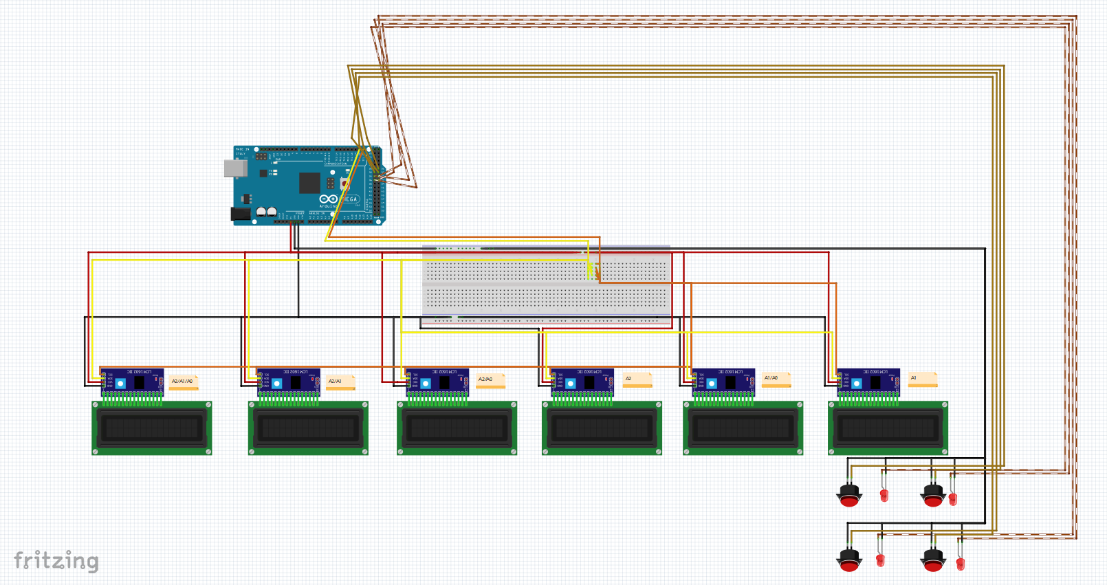
I don't know. I know that when I press the buttons, the screens do not change display. They all display at the same time
Thanks for the diagram. It's helpful. But a spiderweb as most Fritzing diagrams are.
It sounds like you have not done any "divide and conquer" troubleshooting with simpler sketches and tests.
Did you at all investigate the I2C pull up resistor issue I mentioned?
It's been a week since you last posted.
Start with just one LCD, and two buttons.
When you have that figured out, the rest will be much easier.
Thank you for your answer.
The solution for the I2C pull up resistor is put a resistance of 2.7 Kohm or 4.7 Kohm ?
And for my code, it is correct ?
Thank you in advance fo your answer ![]()
None of those questions can be answered yet, because you do not answer questions.
I ask you about pull up resistors, you post the same diagram again with no explanation, and ask again about pull ups. You have not investigated or made measurements.
You ask about code. You were asked, in what way doesn't it work, you did not answer.
If you want help, you have to answer all the questions you are asked. A question is as much a route to a solution as is a statement.
This topic was automatically closed 180 days after the last reply. New replies are no longer allowed.