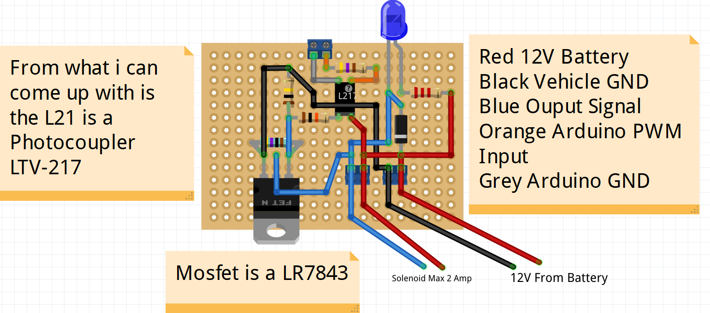
Here is the best I can come up with on this board for the circuit. I am looking to integrate it into my own PCB and I was curious if I could make this better with a mosfet driver or changing some resistors. I have already added the green 4.7kOhm resistor across gate and source to make it work. Another thing is it does not work without 5v and I am using a 3V3 board (due) and sending data to 5V board (Nano) to run this circuit. Would driving with 3V3 be feasible?

Give us a chance, show us a schematic. ![]()
What is the minimum pulse width you are needing to pass ?
Why are you paralleling a 4.7k with the 100k ?
The gate 10k looks like it forms a voltage divider with the 100k//4.7k ![]()
Not sure what you are wanting for that top screw terminals go to arduino bottom goes to battery and solenoid.
Not sure right now about 20% duty cycle is plenty.
A couple guys looked at it a while ago and said to put the 4.7k in as the gate was staying charged.
not sure on the voltage divider why its there
Showing us your schematic will allow us to have a better discussion.
2 Likes
what information are you missing?
Hi, @darmfield12
We are missing a proper schematic (circuit) diagram of your project?
Thanks.. Tom... ![]()
![]()
![]()
![]()
![]()
1 Like
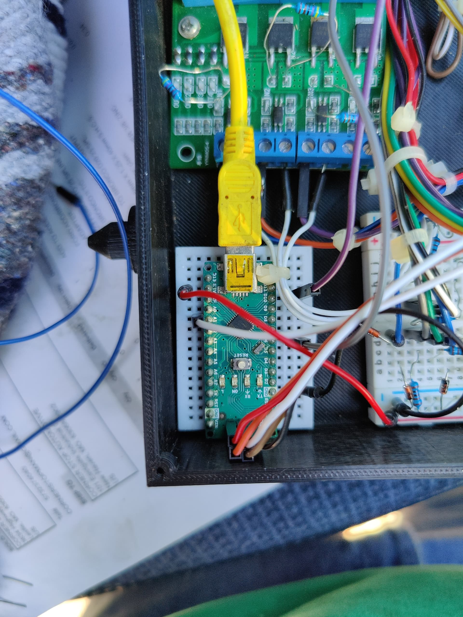
Top Picture is the overall picture.
Bottom is when I added the Nano since I could not get the due to work properly with the PWM board. But All the Nano does it get an input from due and reads a pressure through analog pin and trys to match the actual pressure with the desired pressure the due feeds it though SPI. The other side of the board goes to the solenoid and truck battery

When asking hardware questions it is expected you will supply a schematic.
Please do so in the future.
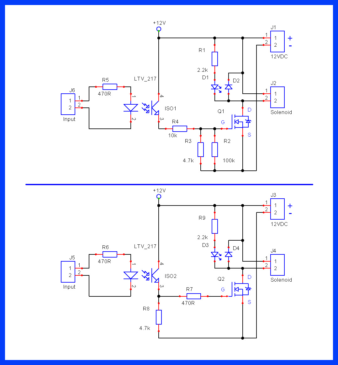
As you can see, there are several problems with your design, (assume this reflects it correctly).
-
In the top circuit, R4 and R3 form a serious voltage divider.
-
R5 could be smaller, try 220R.
-
Try the bottom circuit and report back.
1 Like
What program did you make that in? Also I would prefer to move away from this board and go with through hole components if possible so that I can put it on perf board for ease of changing components and building. Would a IRLB8721PBF work without the photocoupler?
I use an old (no longer available) circuit drawing program.
You can look at KiCAD or EasyEDA (free) to draw schematics.
-
I suggest you use a DIP 4N32 Opto Isolator, (CRT is 500%).
-
A DIP 4N35 could also be useful.
-
If you want isolation between the Arduino and the MOSFET, you need a Opto Isolator.

- A MOSFET only solution will work but there is no isolation.
An IRF3708 would work at a Vgs of 3V3.
Those FET boards like the photo in the OP aren't so good with 3V logic.
They do better if you jumper out (or bypass) the LED in series with each input.
PE - darmfield, that's right; we were working on this a couple of years ago.
1 Like
Yes its been decently work since just want to make smaller and not have to run two different boards just for the 5v. The input LED is gone and pads are soldered together where it was but still never quite worked right with 3V3.
What's the difference with the 4n35 and the 4n32.
Seems to be hard to find since they are discontinued
Amazon.com has lots.
4N35 has a CTR of 100% with a max. Ic 50mA.
4N32 has a CTR of 500% with a max. Ic 100mA.
If what i assuming is correct using the optocoupler the gate voltage would be the 12v from the battery? Therefore the IRLB8721 mosfets I have should work just fine or am I missing something?
-
Yes it should work.
-
Try the lower circuit from post #8.
-
The input LED resistor can be 220R.
-
Measure the voltage across R8 when Opto is ON then when OFF; should be ≈ 11.5V and 0V.
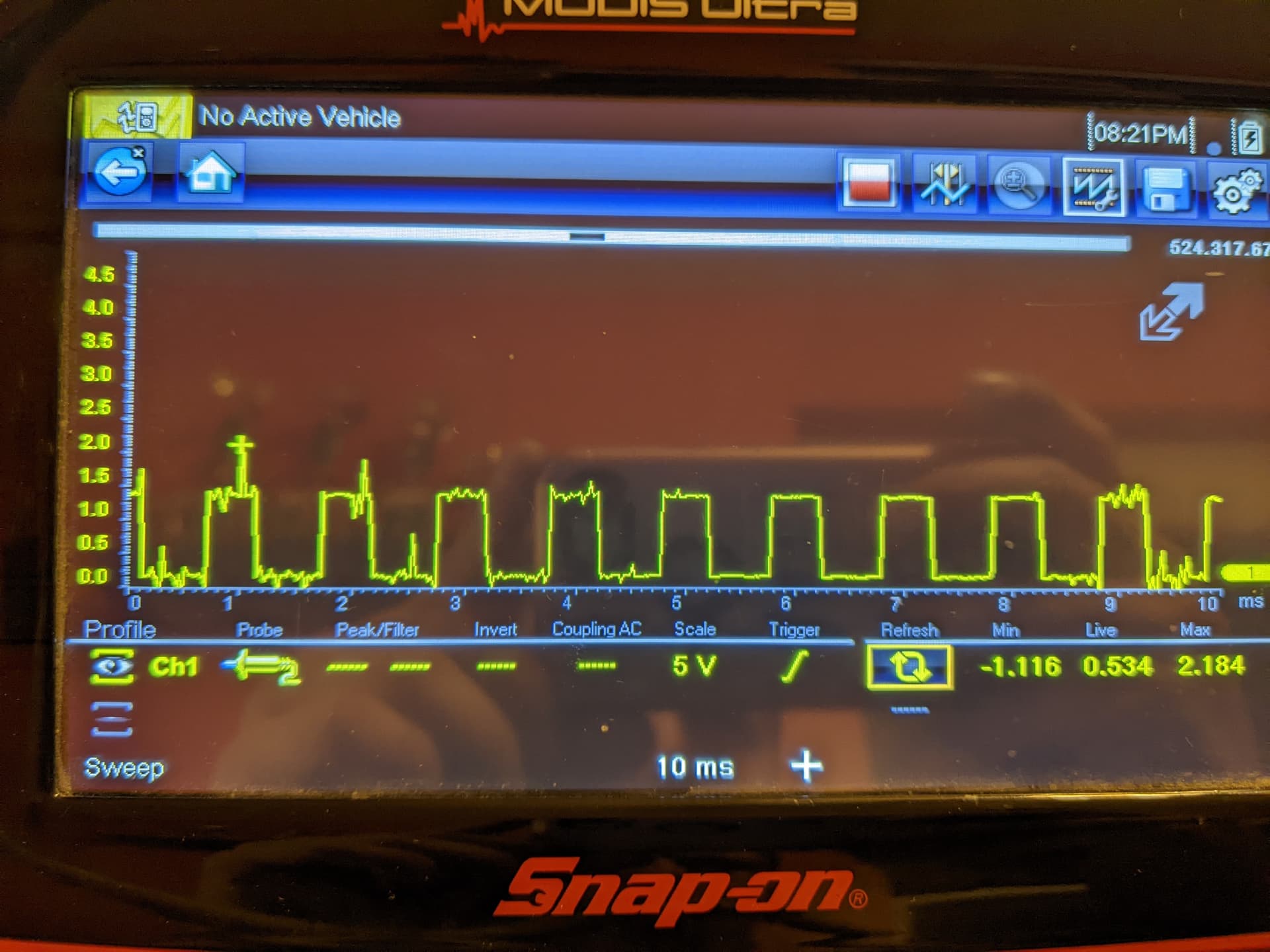
Gonna need some troubleshooting advice here I have converted to 4n35 and IRLB8721 Wired like lower of Post 8 And I can't seem to get a PWM out of the 4n35 Any good way of checking.
We need to see good images of the physical connections.
yellow and blue on bottom left is 6.8 volts from power supply and 5v on other rail from arduino running 5v board to make sure it works with that first

void setup() {
  // initialize digital pin LED_BUILTIN as an output.
  Serial.begin(9600);
  pinMode(3, OUTPUT);
  pinMode(A0, INPUT);
}

// the loop function runs over and over again forever
void loop() {
  analogWrite(3, map(analogRead(A0),0,1023,0,255));  // turn the LED on (HIGH is the voltage level)
  Serial.println(map(analogRead(A0),0,1023,0,255));
                   // wait for a second

}
I have a lab scope ready if you want me to hook to pins