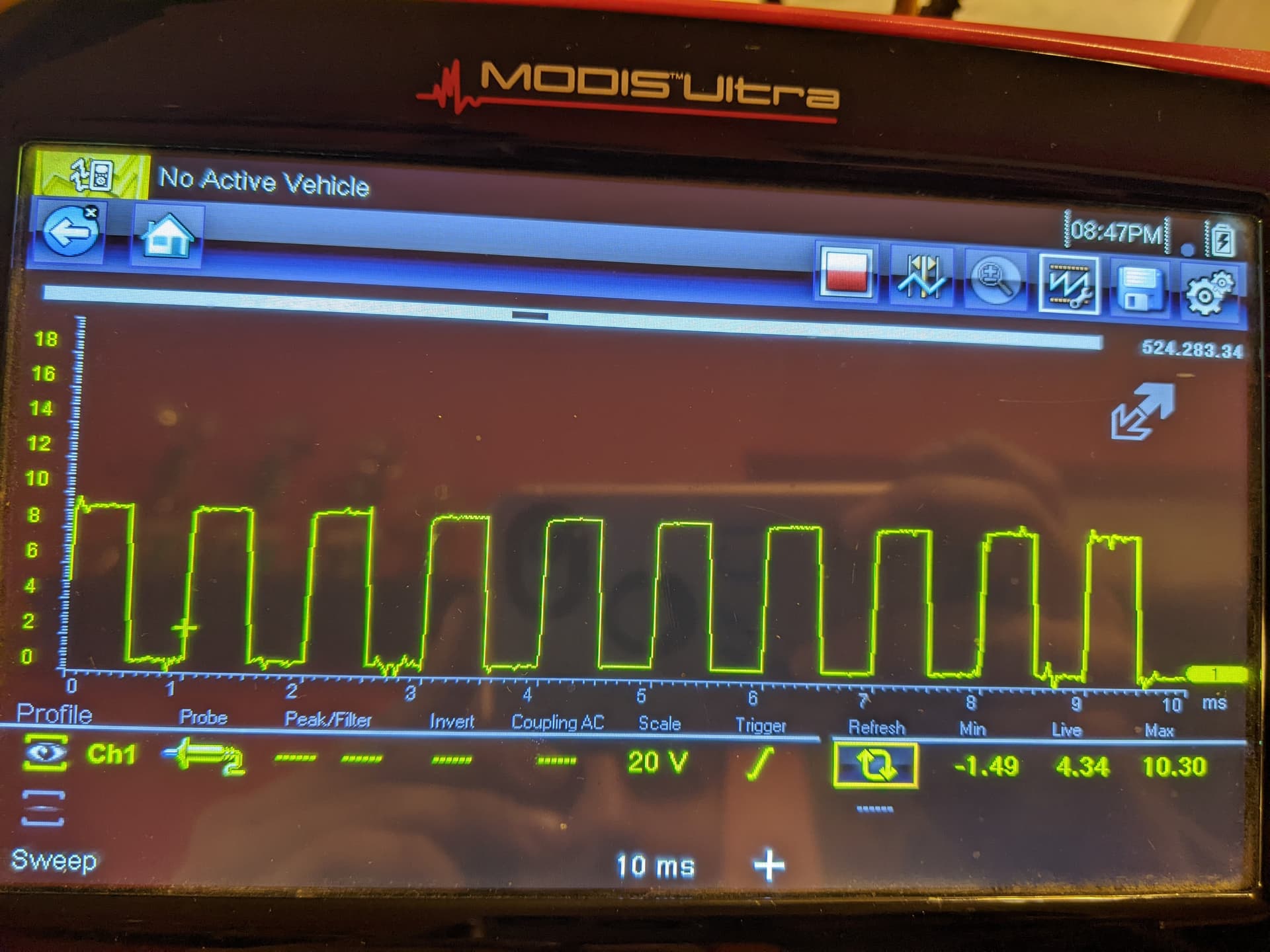
4N35
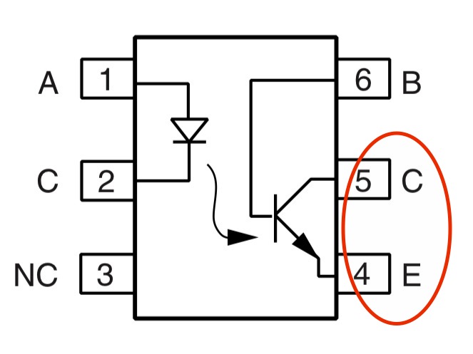
-
You have not wired the Opto properly.
-
Don’t use pin 6

-
Use pins 5 (collector) and 4 (emitter).

You can experiment with connecting pin 6 to GND through a base resistor.
Start with a 100k, this should/might square the waveform a bit better than we see now.
Looks pretty good to you correct?
You can experiment with connecting 4N35 pin 6 to GND through a base resistor.
Start with a 100k, this should/might square the waveform a bit better than we see now.
Nice, looks good.
There are tons of alternatives, e.g. the PC817 (also comes in multi packs, like the PC847 with four optos in one IC).
Given a choice I'd always go with current parts, not discontinued parts. They're discontinued for a reason, usually because they're obsolete: better & cheaper alternatives have become available.
Hello all! new to the site. Very interested in building one of these for my vehicle. My ECU is fried and I would like to build this Transmission controller. This post is directed to darmfield12. It would be much appreciated if you could contact me directly.
Thanks, Sean