I'm using these rgb led strips (the "analog" ones). At the moment I am powering them using MOSFETs, who's gate is being driven by an Arduino nano R3 pin. There is a resistor (I think between 220 and 1k ohm) between the pin and the gate of the MOSFET to avoid over current. I can see an issue with this which is the gate isn't charging up fast enough due to the limited current.
I've heard of something called a "MOSFET driver" which drives the gate of the MOSFET with sufficient current.
Are these necessary in my application, or should I use the driver chips? Should I worry that the MOSFET isn't receiving enough current from the Arduino pin?
You found the reason I suggest not using gate resistors, you cannot over drive it with an arduino. The MOSFET driver will push amps into the gate causing it to switch fast. If not properly done you will generate EMI and RFI interference. Remember the gate is capacitive and the resistor forms a slow RC circuit. If you connect directly to the Arduino it will act as a current source for a few nano seconds as it decays to about 0 on the current. This response is to help you get started in solving your problem, not solve it for you.
Good Luck & Have Fun!
Gil
gilshultz:
You found the reason I suggest not using gate resistors, you cannot over drive it with an arduino. The MOSFET driver will push amps into the gate causing it to switch fast. If not properly done you will generate EMI and RFI interference. Remember the gate is capacitive and the resistor forms a slow RC circuit. If you connect directly to the Arduino it will act as a current source for a few nano seconds as it decays to about 0 on the current. This response is to help you get started in solving your problem, not solve it for you.
Good Luck & Have Fun!
Gil
It depends on what FET you are using and how fast you want it to work.
Should I worry that the MOSFET isn't receiving enough current from the Arduino pin?
They don't work by current transfer, it is all about the voltage.
A simple logic level FET will work with a direct output from the Arduino, through a 120R series resistor to the gate works well. The fact the FET turning on slowly is only going to cause more heat, it won't stop it from working. So can we have some real details. Part numbers, schematic and photograph.
ningaman151:
I don't want the MOSFET to be in the switching state; where it has a high drain source resistance, dissipating a lot of heat.
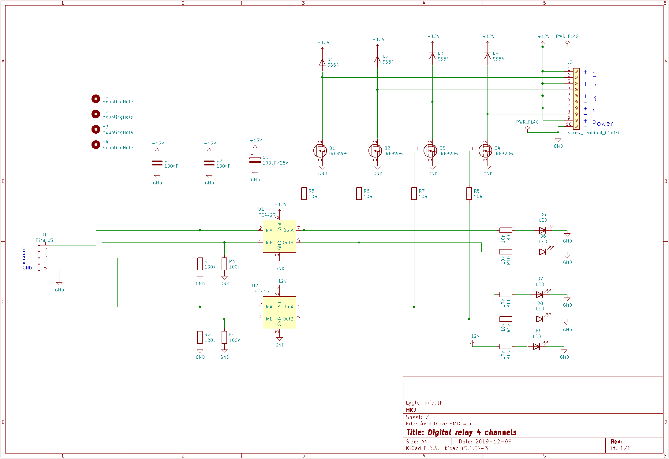
Look at my project here: Digital Relay 4 Channels 12V
There I use a drivers to turn a couple of mosfets on fast.
The drivers can deliver more than 1A to the gate.
HKJ-lygte:
Look at my project here: Digital Relay 4 Channels 12V
There I use a drivers to turn a couple of mosfets on fast.
The drivers can deliver more than 1A to the gate.
Hey thank you for your reply; I had a look at your project. I'm sorry but I didn't understand what was going on in it though.
It's pretty simple. The TC4427 is a buffer chip which takes two TTL logic level (or any CMOS logic level) inputs and buffers them to drive levels of its full supply voltage with Schmitt trigger action so that there is no hesitation, on its two outputs.
You connect it to a 12 V supply and it will drive FETs with a 12 V level swing so you do not need to use logic-level FETs.
Paul__B:
It's pretty simple. The TC4427 is a buffer chip which takes two TTL logic level (or any CMOS logic level) inputs and buffers them to drive levels of its full supply voltage with Schmitt trigger action so that there is no hesitation, on its two outputs.
So does this chip only work with high and low signals (no analog values?)
It's pretty simple. The TC4427 is a buffer chip which takes two TTL logic level (or any CMOS logic level) inputs and buffers them to drive levels of its full supply voltage with Schmitt trigger action so that there is no hesitation, on its two outputs.
You connect it to a 12 V supply and it will drive FETs with a 12 V level swing so you do not need to use logic-level FETs.
What is the purpose o the 10R resistors between the output of the TC4427 and the MOSFET gates? Also what about the screw terminal? And also the LEDs with the 10k resistors at the output of the chip?
ningaman151:
What is the purpose o the 10R resistors between the output of the TC4427 and the MOSFET gates? Also what about the screw terminal? And also the LEDs with the 10k resistors at the output of the chip?
To reduce ringing and slow on/off (reduces RF generation) down if you mount larger resistors.
The screw terminals are for mounting larger wires, the jumper wires used on breadboards are not very good when you get into the ampere range.
The leds are for showing the status, it is considerable faster to find bugs/errors when you directly can see if a the board is powered and the output is on.
HKJ-lygte:
To reduce ringing and slow on/off (reduces RF generation) down if you mount larger resistors.
The screw terminals are for mounting larger wires, the jumper wires used on breadboards are not very good when you get into the ampere range.
The leds are for showing the status, it is considerable faster to find bugs/errors when you directly can see if a the board is powered and the output is on.
Can't we just connect the output of the TC44227 to the MOSFET gate directly? Wouldn't that give faster performance?
HKJ-lygte:
Yes. The idea with the resistors are that you increase them if you want to run longer cables, this way you do not disturb all AM radios in the area.
Sorry I don't understand what you mean. Won't adding resistors make the MOSFETs perform slower?