Zapro:
Faster switchoff? What on earth are you talking about man ... There is no way in hell to get a mechanical relay to switch off any faster, other than to remove the power to it.
// Per.
Better to read up on a subject before posting what turns out to be nonsense. Using a resistor as a snubber leads to much faster collapse of the magnetic field in the relay than a free-wheel diode, allowing the spring in
the relay to snap the contacts apart quicker as the magnetic force it is countering falls rapidly.
MarkT:
Using a resistor as a snubber leads to much faster collapse of the magnetic field in the relay than a free-wheel diode, allowing the spring in the relay to snap the contacts apart quicker as the magnetic force it is countering falls rapidly.
But presumably there's a down-side, or all the gazillion examples using diodes would have resistors instead?
wilfredmedlin:
But presumably there's a down-side, or all the gazillion examples using diodes would have resistors instead?
You will find that I mostly covered that in my answer above.
Short:
It exposes the transistor to higher voltages, but that is calculatable and the breakdownvoltages are in the datasheet.
In addition if without an additional diode (for whatever reason), it draws more current in the on state.
It´s sorted out and the circuit is working fine with the relays.
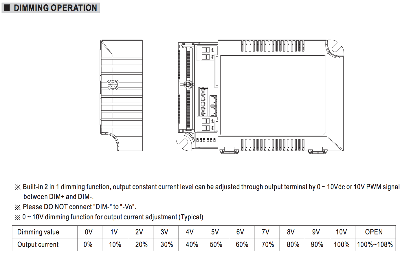
I also have a electronic dimmer to control with arduino. It accepts a signal 0-10VDC.
It needs very little current to work. Should I add a resistor in series with the diode, in order to limit current flow, or is the dimmer input acting like a resistor it self?
Well how much current does it TAKE, not NEED?
(An optocoupler doesn't need a lot of current, but that doesn't keep it from frying if you just connect it to 5V)
Thats the problem I cant find it in the datasheet..
It has over-voltage,over-heating and short circuit protection.
Do you think it will be okay without a resistor added?
Put a resistor and measure the voltage over the resistor. If it is essentially 0V, then the input is high impedance, if it is not 0V, then you can calculate the current and the resistance of the input.
Confused.
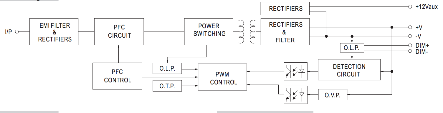
Are you trying to turn a Meanwell LED driver off by switching (shorting) the DIM pins with a relay?
The datasheet states 10volt and 100k. A current of ~100uA.
A transistor (or the transistor in an opto coupler) could be far better than a relay.
Leo..
Wawa:
Confused.
Are you trying to turn a Meanwell LED driver off by switching (shorting) the DIM pins with a relay?
The datasheet states 10volt and 100k. A current of ~100uA.
A transistor (or the transistor in an opto coupler) could be far better than a relay.
Leo..
Don´t get confused. I am using relays for shutting off the AC LOAD when the LED driver is not in use. I noticed it is creating a buzzing sound and gets a little hot when the LED lighting is dimmed very low (or even off). Also I thought it was a good idea to have the ability to control the AC line, from a security aspect.
I will be using a transistor to control the 10volt signal. Should I then add a resistor in series with the diode, to limit the current flow to 100uA or is it already taken care of in the LED driver as you suggested?
Couldn't find that information in the datasheet...
Ahh, got you now. Mains power switching with that relay is ok.
Yes, coil whine (buzzing) of switching supplies can be audible, and depending on the dim/off level.
The DIM inputs can AFAIK be controlled with a 100k pot (100k being full brightness, and 0k being off).
Or with a voltage (0-10volt).
Or with a (PWM) switch (transistor or opto transistor).
No diodes needed there, because you're just sinking a small current.
Leo..
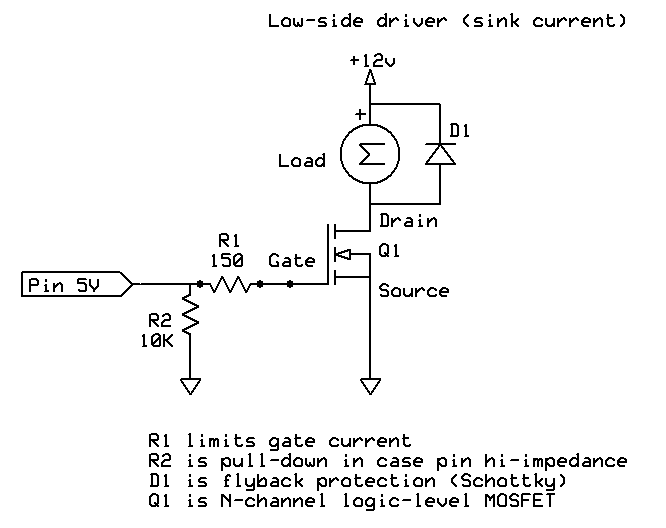
The OLD circuit is almost right, the new one is not.
DIM(-) should go to Arduino ground and fet source.
DIM(+) to drain.
NO supply (V-in) to the breadboard.
100-220ohm resistor from Arduino signal pin to gate.
10k resistor from Arduino signal pin to Arduino ground.
You could just use a small signal transistor (BC547 etc) with 1k base resistor for all of this.
Leo..
Now it works like a dream. Sorry to bother you so much with this with this.
I have read a lot, and watched a couple of tutorials, still I am trying to understand it...
Can you post a copy of your final working schematic to help finish the thread for anyone using this to help with their project?
Thanks.. Tom..
Sure, its a pretty large project trough. I am working on finishing the schematic. If you want I can post a schematic of things we have discussed in this thread only, so it does not get confusing
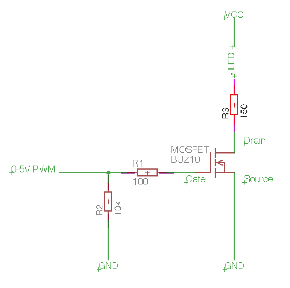
One final question about using transistors. I dont quite get it... What is actually reducing the flow of electrons in this circuits? As an example I have uploaded a schematic on using a MOSFET to dim a high power LED. I will need a resistor, right? When should I use a diode in such a circuit?
Sumitsubo:
One final question about using transistors. I dont quite get it... What is actually reducing the flow of electrons in this circuits?
Where? In the light circuit the LED, the resistor and to a small extend the R_DS(on) of the MOSFET.
The gate of a MOSFET is only a capacitor. After it is filled, it does not conduct anymore. To avoid large currents from the Arduino pin while charging, R1 is in place.
If the MOSFET was a BJT instead, the base (MOSFET: gate) would be connected to the emitter (MOSFET: source) and R1 would limit the current. Since it would flow continuously, 100Ohm would not be enough.