CrossRoads:
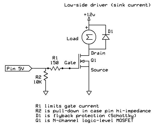
Connect to Gnd if connecting to inductive loads (relay coils, small motors, for example).
If not, the output transistors may not fail immediately, but will eventually. Sooner rather than later if the inductor is larger or running from a higher voltage.
Power supply gnd should also be connected to Arduino gnd to provide a common reference point for all signal levels.
sorry but this I do not understand, what should be conneted to ground?
CrossRoads:
Power supply gnd should also be connected to Arduino gnd to provide a common reference point for all signal levels.
ok this is clear, I will test circuit with shared ground.
I am just testing, and I figure out very strange behavior:
I have 10k resistor in parallel between input pin of UDN2981 and ground.
Purpose is pull down arduino floating voltage when reset or not defined pin mode.
But now I am testing without arduino, as control signal I use 3,3V and when the cround with pull down resistors is not connected to ground of 3,3V power supply all output pins goes high....so ok I was thinking UDN2981 needs pulldown as well.
I am testing maximum load of UDN2981, so I had activated 6 output, each has 100mA load.
But then wierd thing happend, 7th output went high ( but 7th input was not connected to 3,3V ).
So I thought 1 of pulldown resistors has wrong value, I measured by multimeter and really, one resistor had only 3,5K and slowly growing up.
I use chinese resistors from eBay, I thing reason that value of these resistors are very unstable when temperature of package changing?
How to avoid this, should I use higher value as pulldown, for example 20k, will this help? and will be higher value ok for arduino?
EDIT:
ahhh, sorry I had short circuit betwen two input pins 
However chinese resistors are very unstable in the influence of changing temperature
Thanks a lot for your help. Miro