Hi!
I'm new here and studying right now Robotics, and my teacher asked me to move two stepper motors attached to a machine using labVIEW and arduino. Right now I'm having trouble just making a sequence for the motors to move. This devices are placed in some rails and have limit switches in both sides. I would appreciate some help, because right now I cant make the motors move. This is my code. Thank you for your help!!!
Oh, and also some words in the code are in spanish cause I live in there, sorry for the inconvenience.
   #include <Stepper.h>
const int giro360=200; //numero de pasos para completar 360
const int fcminx=11;
const int fcmaxx=12;
const int fcminz=9;
const int fcmaxz=10;
bool ejeX=true;
bool ejeZ=true;

Stepper motor1(giro360,2,3);//eje x (driver izquierdo)
Stepper motor2(giro360,7,8);//eje z (driver derecho)
void setup() {
  pinMode(13, OUTPUT);   //enable
  digitalWrite(3, HIGH);
  digitalWrite(3, HIGH);
  motor1.setSpeed(40);//velocidades de los motores
  motor2.setSpeed(40);

Serial.begin(9600);

  pinMode (fcminx, INPUT_PULLUP);//resistencia interna para asegurar lecturas correctas
  pinMode (fcmaxx, INPUT_PULLUP);
  pinMode (fcminz, INPUT_PULLUP);
  pinMode (fcmaxz, INPUT_PULLUP);

}

void loop() {

//definir booleanos para asegurar que los finales de carrera no están pulsados
bool posicionXminima=(digitalRead(fcminx)==LOW);
bool posicionXmaxima=(digitalRead(fcmaxx)==LOW);
bool posicionZminima=(digitalRead(fcminz)==LOW);
bool posicionZmaxima=(digitalRead(fcmaxz)==LOW);

//secuencia de movimiento
//movimiento para el eje X
if (ejeX){
  if(posicionXminima==LOW) {
    Serial.println("Tope mínimo alcanzado en eje X");
    ejeX=false;
  }

    else motor1.step(-5);

}
else {

if(posicionXmaxima==LOW) {
  Serial.println("Tope máximo alcanzado en eje X");
    ejeX=false;
  }

    else motor1.step(5);
}

if(ejeZ){
 if(posicionZminima==LOW) {
    Serial.println("Tope mínimo alcanzado en eje Z");
    ejeZ=false;
  }

    else motor2.step(-5);

}
else {

if(posicionZmaxima==LOW) {
  Serial.println("Tope máximo alcanzado en eje Z");
    ejeZ=false;
  }

    else motor2.step(5);
}
delay(100);

}
Okay, maybe I didn't explained it well enough.
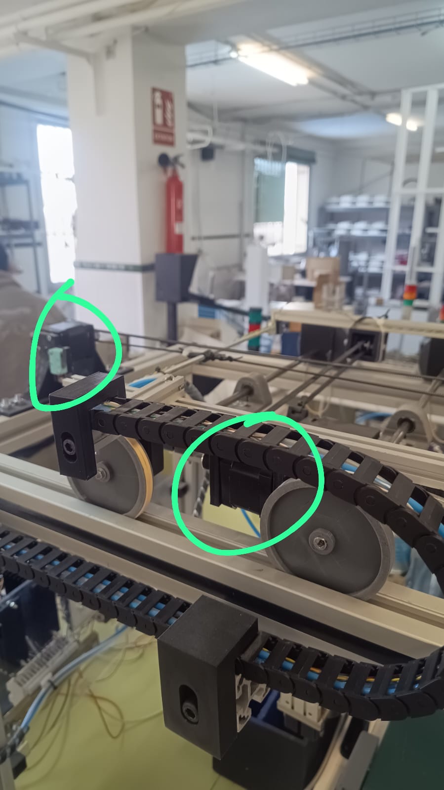
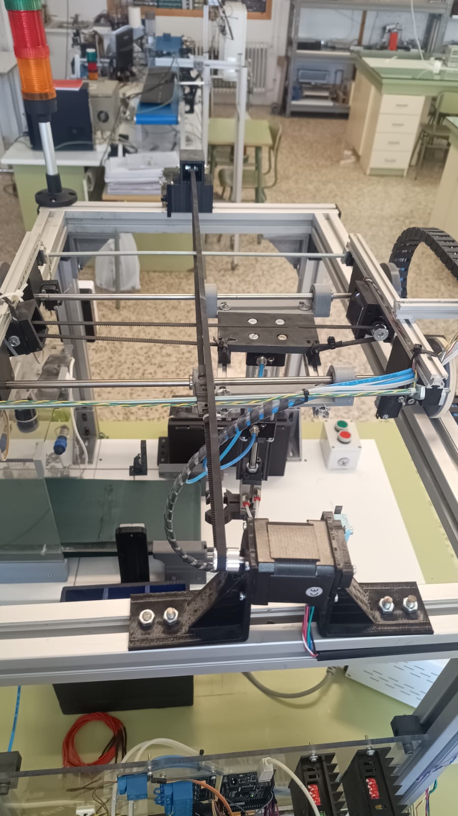
Right now I just want the motors to move slowly. They have attached a device that is intended to move on the X and Z axis with some straps. This device is the one that makes contact with the limit switches.
It seems like you are trying to run before you can walk. Try a simpler sketch, all you need to do is toggle the step pin. Just setSpeed() and runSpeed(). Ideally confirm that you get the expected output, if you don't have a scope or logic analyzer, you can just use an LED.
If you can output a pulse, then the problem is somewhere in the hardware or wiring.
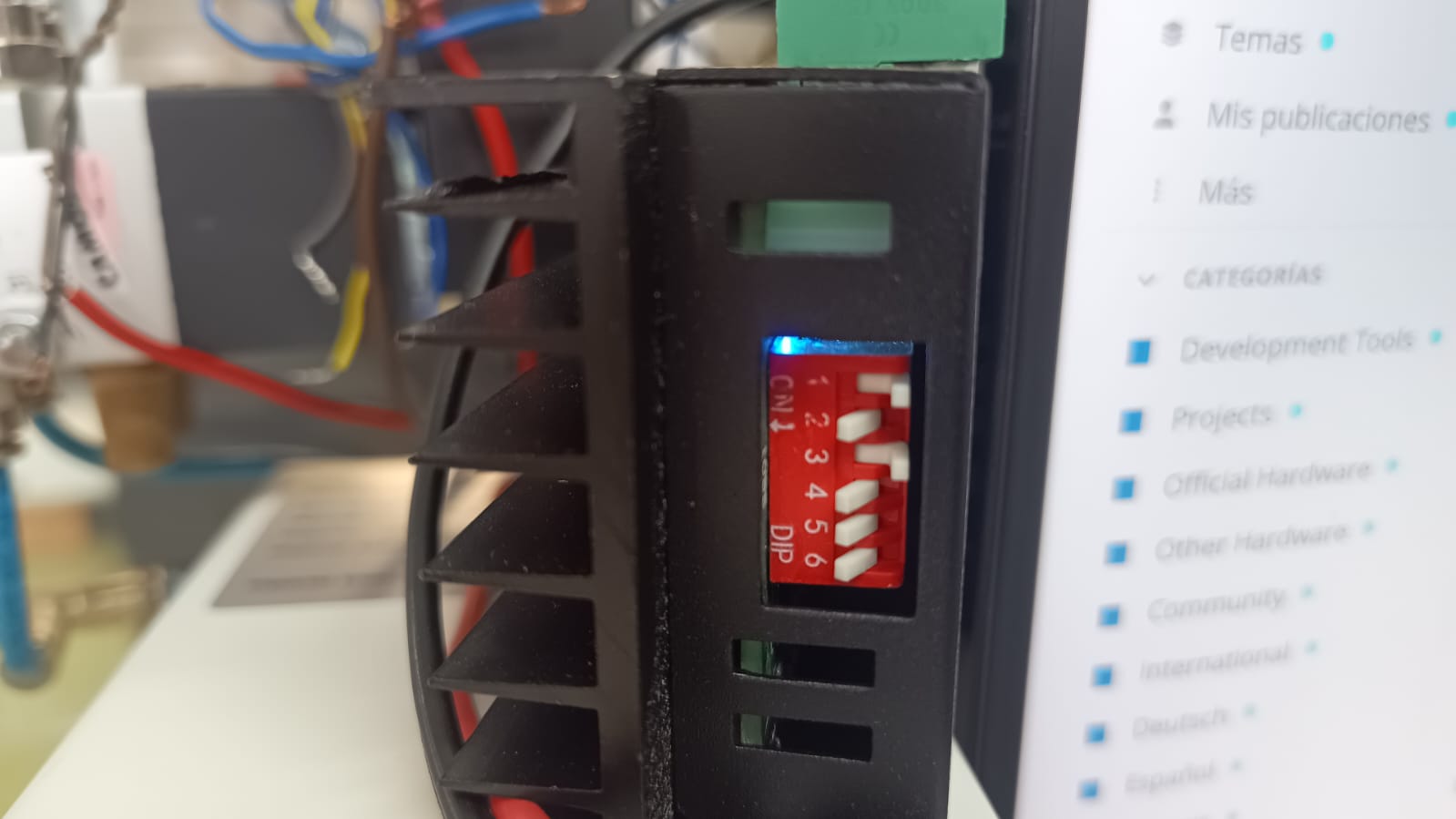
Hey!! Sorry not to respond in a while, but I'm also having a lot of other exams and subjects, so I've been working around in other projects. So, I'm uploading the images here of this ''machine''. The last time I tried I noticed that both motors where heating up a little, and I also heard like pulses, so my guess is that or they are receiveng a signal to stay still, or maybe the signal is not strong enough, I don't really know...
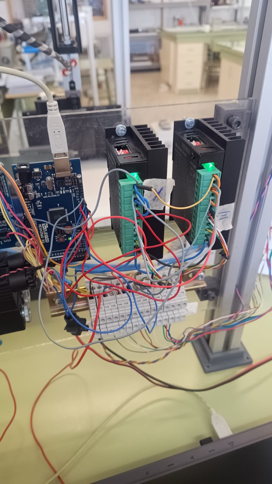
The devices have kind of a messy wiring, but note that there are more people using this so its kind of impossible to keep it clean.
And we don't know anything about them, expect they have nema23 mount.
Anyway, you have current limited to 0.5A by the dip switches , try with 2.0A, (raise switches 5 and 6).
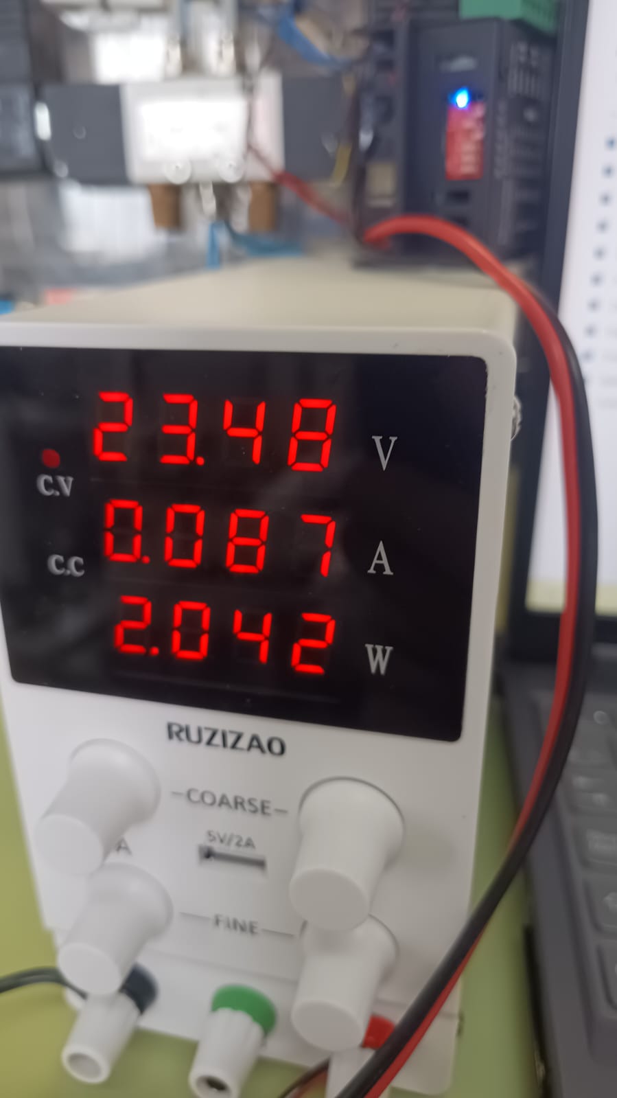
Make sure you don't have current limited by your bench supply.
ok, so I think you are also right and it looks like I want to run before know how to walk, so i'm trying just with a really short version of the program... Both limit switches work perfect but it doesn't seem to move or even trying... I'll try raising those switches.
anyway, here's the code:
#include <AccelStepper.h>

const int pulso = 4;
const int dir = 3;
const int fcmin = 11;   // Final de carrera mínimo
const int fcmax = 12;   // Final de carrera máximo
bool sentido = true;    // true: mover en dirección positiva, false: dirección negativa
AccelStepper motor(AccelStepper::DRIVER, pulso, dir);

void setup() {
  pinMode(13, OUTPUT);   // Pin para habilitar el driver
  digitalWrite(13, HIGH); // Habilitar el driver
  motor.setMaxSpeed(500);
  motor.setAcceleration(250);
  Serial.begin(9600);
  // Configuración de finales de carrera con resistencia interna
  pinMode(fcmin, INPUT_PULLUP);
  pinMode(fcmax, INPUT_PULLUP);
   Serial.println("A mover motores!");
}

void loop() {
  // Lectura de los finales de carrera
  bool Min = (digitalRead(fcmin));
  bool Max = (digitalRead(fcmax));
Serial.print("Estado fcmin: ");
Serial.print(digitalRead(fcmin));
Serial.print(" | Estado fcmax: ");
Serial.println(digitalRead(fcmax));
  // Secuencia de movimiento
  if (sentido) {
    Serial.println("izquierda");
    if (Max) {
      motor.move(100);
        // Mover en dirección positiva
    } else {
      Serial.println("Tope alcanzado");
      digitalWrite(13,LOW);
}
  }
    motor.run();
  delay(2000);
}
Now it's a bit changed because the logic on the limit switches was inverted.
I also had de 5 and 6 switches raised once and my teacher said that current was not supossed to be so big, that maybe it was a shortcircuit. I really don't know
I only know the nema23 mount. So I can only guess that the nominal current is somewhere between 1.5A and 5A.
But I expect that you know more, normally motors have some name plate.
Also your bench supply needs to be able to supply that current.
And your wiring has to match the code. Do you have common anode or cathode wiring? Is enable connected?
If you need support here, you need to post all necessary info.
Okay, yes they have nema23 mount, like is said in the name of the post, the bench supply is able to supply that current, i have common anode connection, and enable is connected and set to HIGH in pin 13