Hello,
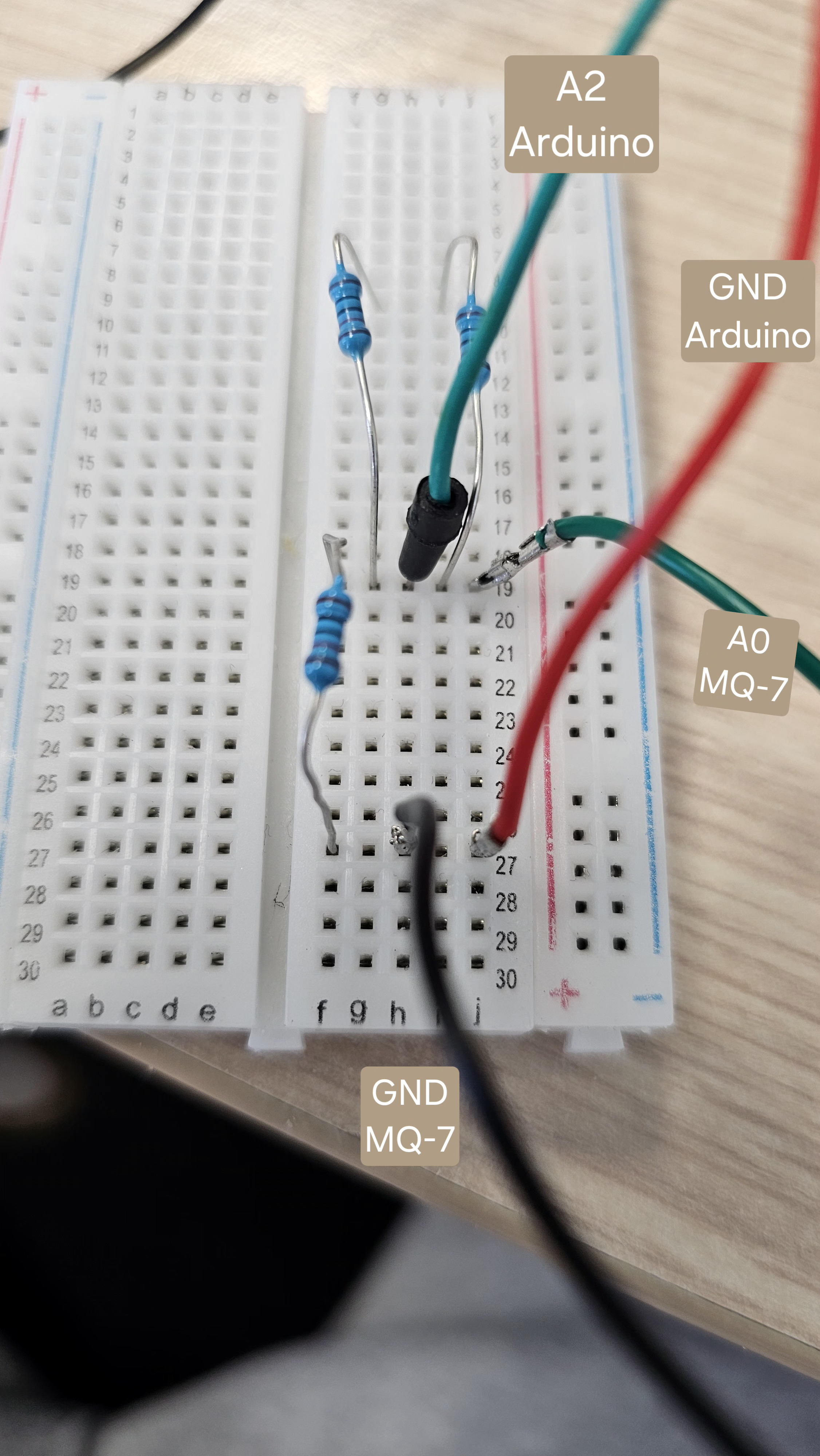
I have an mq-7 connected to my Arduino GIGA R1 WiFi and a 10K resistor. I don't know where to connect my resistor because if I connect it between GND and A0, the green LED is off but I have “correct” values but when I connect it between VCC and A0, the green LED is on but the values become “incoherent ” and after checking around, I learned that the green LED must be on to detect CO. I've included my code below, along with images of my connections.
Thanks in advance for your help
If the purpose of your wiring was to drop the sensor output to 3.3V, you need two resistors to make voltage divider.
You can use other values but R2 needs to be 2x R1.
Thanks for your answer.
Honestly I searched on the internet (I can't find the link) and I was told that I had to connect in 5V and put a 10K resistor but I don't know where or why... Because if I have to connect the MQ-7 in 3.3V I can do it without a resistor because on my board I have 5V or 3.3V.
Could you please give me more information? Honestly, I'm not sure what I should do, and on top of that I can't really find any documentation on the sensor...
Thanks
The problem is that I don't have the right resistors. And will it really make a difference if I use your method rather than just plugging in 3.3V directly without a resistor?
If you power the sensor at 3.3V it probably works as well. The datasheet says it needs 5V but it doesn't hurt to try.
Even reputable vendor suggest that you can use 3.3V:
But if you prefer to make voltage divider and only have 10k resistors, you can put 2 in parallel to make 5k for R1.
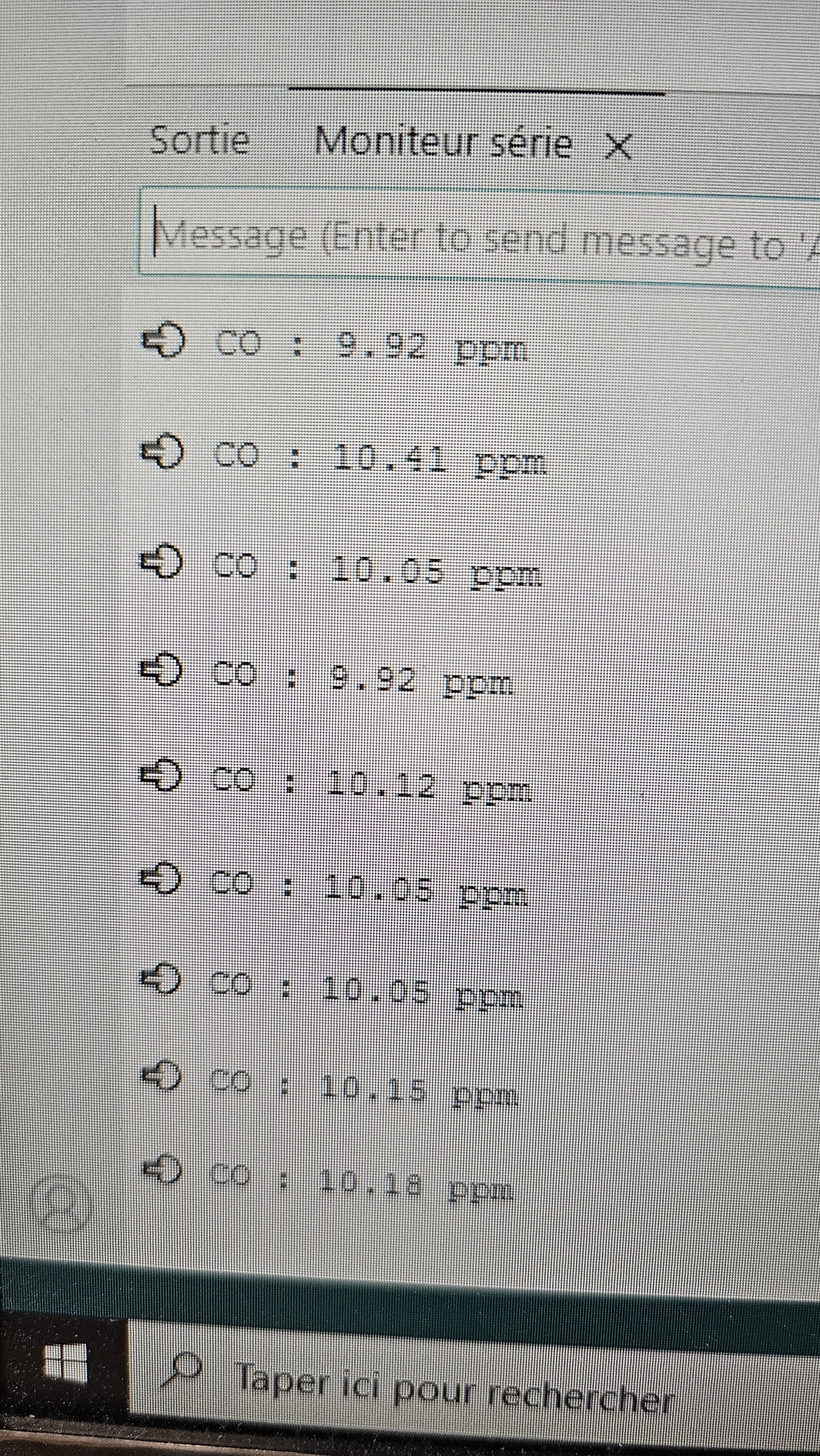
OK, thanks for the clarification, although it doesn't change anything about the green LED. My sensor tells me ~3 ppm but it was the same before I corrected my error... Very strange, isn't it?
Good, because LED indicates a gas level above a set threshold.
Sensor needs some time to heat up. The analog voltage difference at 3ppm is so small that you can't see difference between with/without voltage divider.
Your wiring looks correct now. But please don't use red wire for GND, it's very confusing!
Is the set threshold internal to the sensor, or do I have to set it? Ok then, that's normal. Yes, sorry for the confusion, it was the only long enough wire I had on hand.
So you want me to keep it like that? Above I sent some screenshots where I had similar values. The idea is that if the CO level is too high, my GSM module sends me an alert SMS. So it's me who defines the limit values for which the GSM sends me a message. So my previous set-up may not be disturbing, given that I have control over the parameters...? The problem is that I can't calibrate my MQ-7 because I don't have a “real” CO sensor to hand.
If you can give me your opinion that would be great, thanks for everything.
You are right, my mistake not to dig in to the docs. But OP doesn't have Waveshare module, so the resistor has likely different value, probably 10k from reference design.
Best option would be rebuilding the whole sensor to have heater controlled like it supposed to be. Like here: