Hi
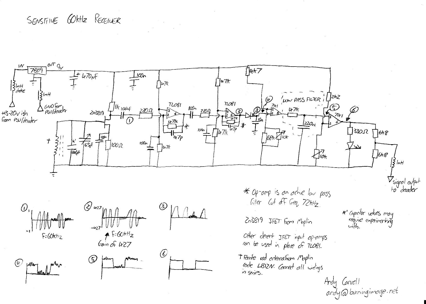
Thank you Perehama for your help, looking into this. Paul_KD7HB the way the MSF Anthorn time coded signal works, is it's transmitted on VLF transmitter (Very Low Frequency) at 60kHz, it makes the data by switching off the transmitter carrier. the sequence start is carrier off for 500ms(.5 second)then on for 500ms, this is second 00, the unique start bit, the next second has a carrier off for between 100, 200, 300,
or off for 100, on for 100, followed by a off for 100ms.
So it's not the level of the pulse it's the duration, (Having said that once decoded it can be converted to data signal, of either TTL or RS232, with another decoder and MAX 232 chip)
These timed outages form bit A and bit B, 100ms bit A=0 & bit B= 0, 200ms bit A =1 & bit B =0, 300ms bit A= 1 & bit B =1, I will not write it all up here, you can look it up at NPL (people who operate the atomic clock in uk) website.
These bits are assigned different values using BCD, binary coded decimal system, like say bit A of 17th second(first 16 seconds used for scientific folks) has a BCD value of 80, (1010000 looks like this as BCD number) as carrier off duration for 17th second is 200ms, A=1 B=0
The 18th second has a value of bit A= 40,(101000) so again 200ms bit B is used but not as much as bitA
I think you see the pattern.
Each carrier hole is a second, so 60 seconds= end of 1 minute string, we see then 500ms off and 500 ms on denotes the start of next minute, and it's all starts over again.
Each second has it's different information attached to it, which remains constant, like second17-24 bit A contains year data, seconds 25-29 bit A, contain the month information (bit B could have a value here but it will flag up different part of the time signal) this is just a taste to get the full story look up on the net.
Its down to your system as to how you decode to get the time out of the signal, many use the analog input of the Arduino.
May I say a big thank you to Dr.Jonathan Hare for his postings on this subject, taught me a lot
Tony Smith