Hi Everyone, I'm traying to make my own music led visualizer with MSGQE7, DFMiniPlayer and LED STRING WS2812B 60 LED.
This are all the schema and datasheet that I'm following.
LED STRING
I'm using a laboratory power supply, a resistor of 330Ohm, and a capacitor of 670uF (Reading Adafruit documentation, these are safe values).
LEDPIN = 6, GND in common with Arduino

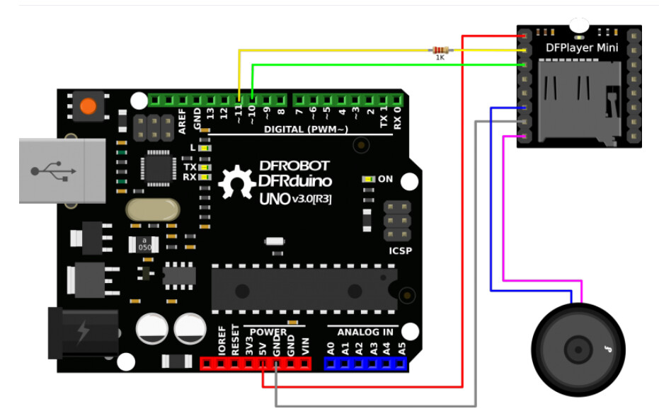
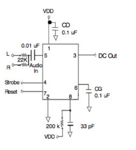
Instead of using SPK_1/2, I'm using DAC_R/L. These pins are both connected to a jack female (for external speaker) and PIN 5 of MSGQE7,

Both DFMini and LED (Adafruit/FastLed) work with their own libraries.
MSGQE7: [datasheet](https://mix-sig.com/images/datasheets/MSGEQ7.pdf)

I'm actually following this schema, but I've connected only DAC_R, so remove L and 1 22 kohm resistor
To test this CHIP I'm actually doing this step:
-
Grounding ADKEY_1 of DFPlayer to start the music
-
I'm running this code to read all the possible frequencies, but I don't understand if there is something wrong.
int strobePin  = 2;    // Strobe Pin on the MSGEQ7
int resetPin   = 3;    // Reset Pin on the MSGEQ7
int outPin     = A0;   // Output Pin on the MSGEQ7
int level[7];          // An array to hold the values from the 7 frequency bands

void setup() {
  Serial.begin (9600);

  // Define our pin modes
  pinMode      (strobePin, OUTPUT);
  pinMode      (resetPin,  OUTPUT);
  pinMode      (outPin,    INPUT);

  // Create an initial state for our pins
  digitalWrite (resetPin,  LOW);
  digitalWrite (strobePin, LOW);
  delay        (1);

  // Reset the MSGEQ7 as per the datasheet timing diagram
  digitalWrite (resetPin,  HIGH);
  delay        (1);
  digitalWrite (resetPin,  LOW);
  digitalWrite (strobePin, HIGH);
  delay        (1);
}

void loop() {
   // Cycle through each frequency band by pulsing the strobe.
  for (int i = 0; i < 7; i++) {
    digitalWrite       (strobePin, LOW);
    delayMicroseconds  (100);                    // Delay necessary due to timing diagram
    level[i] =         analogRead (outPin);
    digitalWrite       (strobePin, HIGH);
    delayMicroseconds  (100);                    // Delay necessary due to timing diagram
  }

  for (int i = 0; i < 7; i++) {
    Serial.print       (level[i]);
    Serial.print       ("   ");
  }

  Serial.println ();
}
This is the actual output (Almost same values in loop)

Moreover, I've ran several scripts trying to make a music visualizer, but all of them doesn't works.
Here one example:
It turns on the led (defined in setup) but there isn't any effect.
//Neopixel main script
#include <Adafruit_NeoPixel.h>

#define PIN 6 //strip pin
int analogPin=0; //A0 pin for reading frequency
int strobePin=2; //Ask MSGEQ7 for data
int resetPin=3; //End communication with MSGEQ7
//int spectrumValue[7]; //Array for frequencies
int filter=80;
int highest;
int rotation=0;
int rotationdelay=0;

int pattern = 0;


Adafruit_NeoPixel strip = Adafruit_NeoPixel(60, PIN, NEO_GRB + NEO_KHZ800);

//Define Specific colors
uint32_t red = strip.Color(255, 0, 0);
uint32_t orange = strip.Color(255, 127, 0);
uint32_t yellow = strip.Color(255, 255, 0);
uint32_t green = strip.Color(0, 255, 0);
uint32_t blue = strip.Color(0, 0, 255);
uint32_t purple = strip.Color(75, 0, 130);

void setup() {
  //Serial.begin(9600); //Debugging serial port
  /**
  pinMode setup for MSGEQ7
  **/
  strip.begin();
  strip.show();
  pinMode(analogPin, INPUT);
  pinMode(strobePin, OUTPUT);
  pinMode(resetPin, OUTPUT);
  analogReference(DEFAULT);
  digitalWrite(resetPin, LOW);
  digitalWrite(strobePin, HIGH);
}

void loop() {
  if(pattern ==0){
      colorLoopProgression();
  }else if(pattern == 1){
      RainbowEqualizer();
  }
}

void RainbowEqualizer(){
  digitalWrite(resetPin, HIGH);
  digitalWrite(resetPin, LOW);

  int spectrumValue[6];
  for (int i = 0; i < 6; i++)
  {
   digitalWrite(strobePin, LOW);
   delayMicroseconds(30); // to allow the output to settle
   spectrumValue[i] = map(analogRead(analogPin), 0, 1023, 0, 9);
   setPixel(i*10, i*10+spectrumValue[i]);
   setReverse(i*10, i*10+spectrumValue[i]);
   strip.show();
   digitalWrite(strobePin, HIGH);
  }
  delay(30);
}

  void colorLoopProgression(){
    int spectrumValue[7];
    digitalWrite(resetPin, HIGH);
    digitalWrite(resetPin, LOW);
    for (int i=0;i<7;i++){
      digitalWrite(strobePin, LOW);
      delay(10);
      spectrumValue[i]=analogRead(analogPin);
      spectrumValue[i]=constrain(spectrumValue[i], filter, 1023);
      spectrumValue[i]=map(spectrumValue[i], filter,1023,0,255);
      //Serial.print(spectrumValue[i]);
      //Serial.print(" ");
      digitalWrite(strobePin, HIGH);
    }
    //Serial.println();

    highest =0;
    for(int i=0; i<7; i++){
      if(spectrumValue[i]>spectrumValue[highest]){
        highest = i;
      }
    }
   // Serial.println(highest);
    for(int i=30; i<60; i++){
      if(i<30+(spectrumValue[highest]/9)){
        int highestt=0;
        if(highestt==0){
          strip.setPixelColor(i, Wheel(rotation+(spectrumValue[highest]/6)+(highest*8)));
        }
        else if(highest==1){
          strip.setPixelColor(i, strip.Color(spectrumValue[highest], (255-spectrumValue[highest])/2, 0));
        }
        else if(highest==2){
          strip.setPixelColor(i, strip.Color(255-spectrumValue[highest], spectrumValue[highest], 0));
        }
        else if(highest==3){
          strip.setPixelColor(i, strip.Color(0, spectrumValue[highest], 0));
        }
        else if(highest==4){
          strip.setPixelColor(i, strip.Color(0, 0, spectrumValue[highest]));
        }
        else if(highest==5){
          strip.setPixelColor(i, strip.Color(75, 0, 130));
        }
        else if(highest==6){
          strip.setPixelColor(i, strip.Color(100,100,100));
        }

      }
      else{
        strip.setPixelColor(i, strip.Color(0,0,0));
      }
    }
    for(int i=30; i>0; i--){
      if(i>30-(spectrumValue[highest]/9)){
        int highestt=0;
        if(highestt==0){
          strip.setPixelColor(i, Wheel(rotation+(spectrumValue[highest]/6)+(highest*8)));
        }
        else if(highest==1){
          strip.setPixelColor(i, strip.Color(255, 127, 0));
        }
        else if(highest==2){
          strip.setPixelColor(i, strip.Color(255, 255, 0));
        }
        else if(highest==3){
          strip.setPixelColor(i, strip.Color(0, 255, 0));
        }
        else if(highest==4){
          strip.setPixelColor(i, strip.Color(0, 0, 255));
        }
        else if(highest==5){
          strip.setPixelColor(i, strip.Color(75, 0, 130));
        }
        else if(highest==6){
          strip.setPixelColor(i, strip.Color(100,100,100));
        }
      }
      else{
        strip.setPixelColor(i, strip.Color(0,0,0));
      }
    }
    if(rotationdelay>=1){
      rotation++;
      rotationdelay=0;
    }
    rotationdelay++;
    strip.show();
  }

  void setPixel(int start_bit, int pixelValue){
    for(int j=start_bit; j<pixelValue; j++){
      strip.setPixelColor(j, colorChoose(start_bit));
    }
  }


  void setReverse(int start_bit, int pixelValue){
    for(int k=start_bit+9; k>pixelValue;k--){
      strip.setPixelColor(k, 0,0,0);
    }
  }

  uint32_t colorChoose(int start_bit){
    switch (start_bit){
      case 0:
        return red;
        break;
      case 10:
        return orange;
        break;
      case 20:
        return yellow;
        break;
      case 30:
        return green;
        break;
      case 40:
        return blue;
        break;
      case 50:
        return purple;
        break;
    }
  }


  uint32_t Wheel(byte WheelPos) {
    WheelPos = 255 - WheelPos;
    if(WheelPos < 85) {
      return strip.Color(255 - WheelPos * 3, 0, WheelPos * 3);
    }
    if(WheelPos < 170) {
      WheelPos -= 85;
      return strip.Color(0, WheelPos * 3, 255 - WheelPos * 3);
    }
    WheelPos -= 170;
    return strip.Color(WheelPos * 3, 255 - WheelPos * 3, 0);
}
QUESTIONS
-
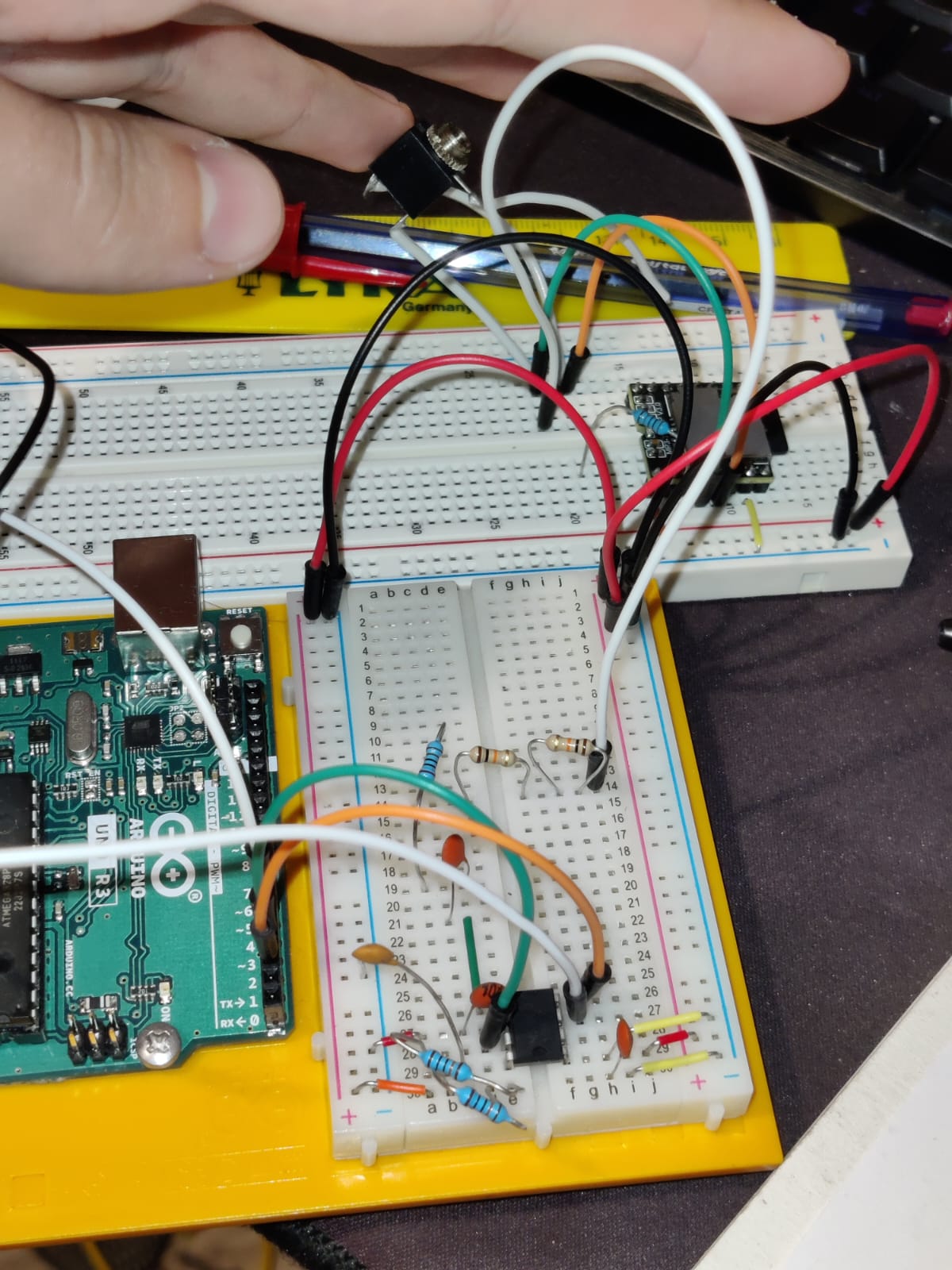
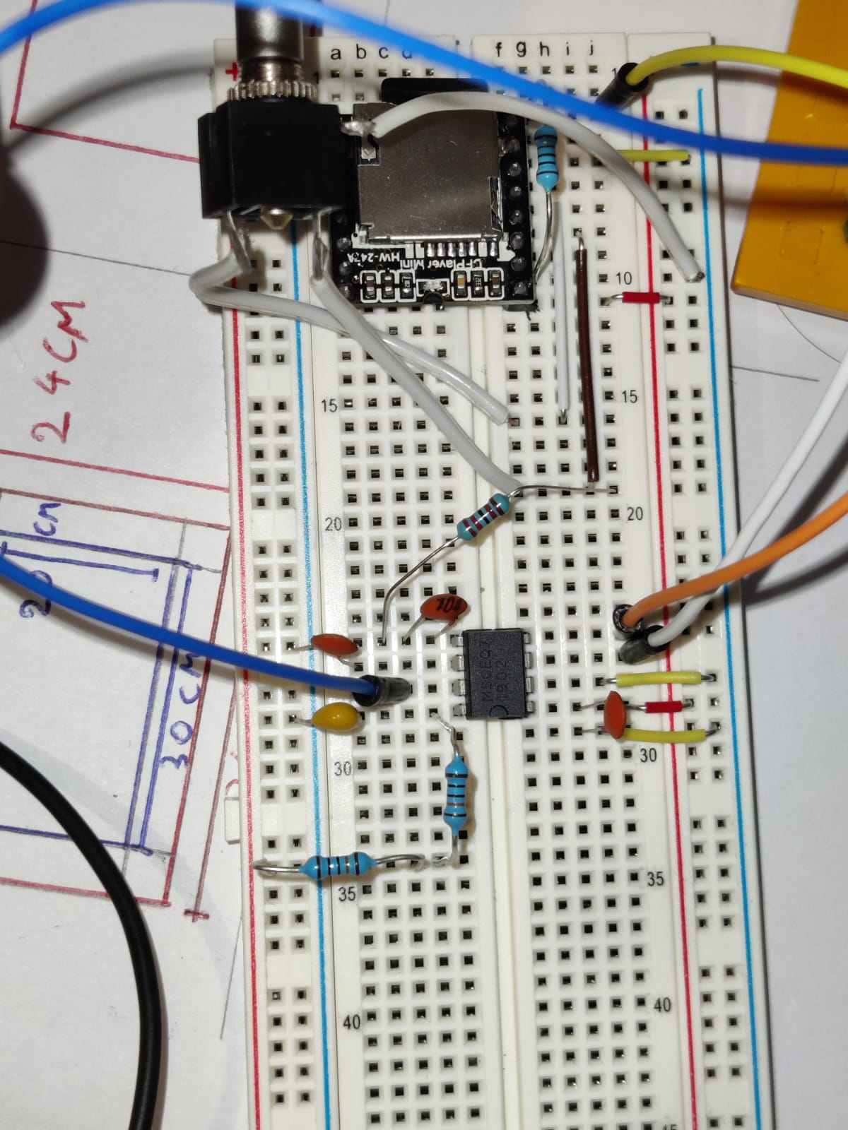
Talking about MSGQE7, It's possible that i've made some connection error? I don't know how to make diagrams, so this is the real circuit (It's following MSGQE7 diagram, the white cable with my finger is DAC_R connecting to pin 5):
-
I'm trying to understand at programming level how to make this effect, but i don't find any documentation around the web. If you can help me by giving any links, it would be wonderful.