Noob here, discovered that using a toggle switch to move a servo is not as straight forward as it sounds (to me anyway) the code I have will rock the first servo (pin 0) from low to high if the switch is high and that is about it. Any help much appreciated.
Cheers,
#include <Wire.h>
#include <Arduino.h>
#include "Mux.h"
#include <Adafruit_PWMServoDriver.h>


#define NUM_SERVOS 2 //The number of servos connected

// called this way, it uses the default address 0x40
Adafruit_PWMServoDriver pwm = Adafruit_PWMServoDriver();

//Servo High/low values
int high = 1815;
int low = 1000;


int servoPin[NUM_SERVOS] = {0,1};

using namespace admux;

//Create MUX
Mux mux(Pin(3, INPUT_PULLUP, PinType::Digital), Pinset(8, 9, 10, 11));

void setup() {
  pwm.begin();//Start Servo Driver
  pwm.setPWMFreq(50);// Analog servos run at ~50 Hz updates
  delay(20);
}


void loop() {
  byte data;
  for (byte i = 0; i < mux.channelCount(); i++) {
    data = mux.read(i); //Read MUX


    if (data == HIGH){

      pwm.writeMicroseconds(servoPin[i], high);
      delay(300);


    }
    else {
      pwm.writeMicroseconds(servoPin[i], low);
      delay(300);
    }
  }
}
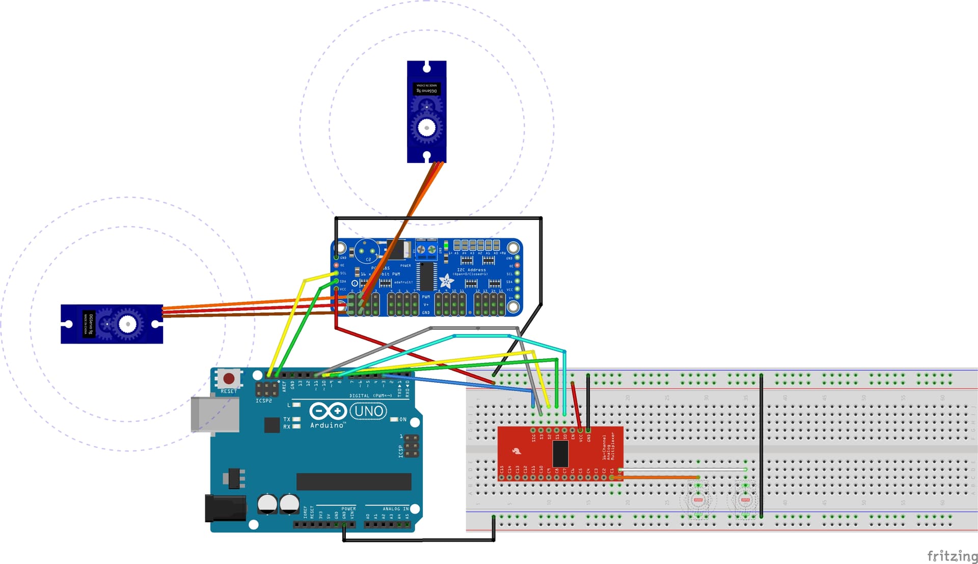
@widgetau Welcome to the forum! While you did very well to post your code in the approved manner in your first post, you need to do more to help us understand your project. A schematic of your project is essential(pen and ink on an envelope, take a picture, post it), as it will explain much about your code that remains mysterious right now.
my thought was i would be the input pin from the MUX and then use it as the servo driver output pin so switch on pin 0 on the MUX controls servo on pin 0
From the looks of it, you're scanning four digital inputs, and setting servos 0, 1, ~, ~ based on the states of the four digitals. I use the ~ as shorthand to indicate that you've indexed beyond the servo pin list end, and therefore have no idea where those settings are going.
See his definitions... they're microsecond values that make sense; however, I don't use the Adafruit driver, so I don't know if that's what it's expecting; my recollection is, they're looking for a number between 0 and 4095, representing proportionately wider pulses from 0-100%, but my memory is fuzzy.
Did say I am a noob to all this as was unable to find a power supply to add to the diagram, however I did say in the text in the diagram post that I had a power supply attached.
So I created this sketch and it worked as expected, moves each servo in turn to the "high" position then pauses and moves them back to "low" with a pause between each move
I can't see what I am missing when I add the MUX...
//Use i for servo pin number test
#include <Wire.h>
#include <Adafruit_PWMServoDriver.h>                             //Include the PWM Driver library

Adafruit_PWMServoDriver pwm = Adafruit_PWMServoDriver(); //Create an object of board 1


//Servo High/low values
int high = 1815;
int low = 1000;

int servoFrequency = 50;    // Servo update frequency, analog servos typically run at ~50 Hz

void setup()
{
  pwm.begin(); //Start board

  pwm.setPWMFreq(servoFrequency); //Set the servo operating frequency

}

void loop()
{
  for (int i=0 ; i<=5 ; i++)   //Cycle through moving 6 servos to high value


    {
      pwm.writeMicroseconds(i, high);
      delay(300);
    }
    delay(3000);

  for (int i=0 ; i<=5 ; i++)   //Cycle through moving 6 servos to low value
    {
      pwm.writeMicroseconds(i, low);
      delay(300);
    }

  delay(500);
}