My arduino keeps disconnecting from the pc

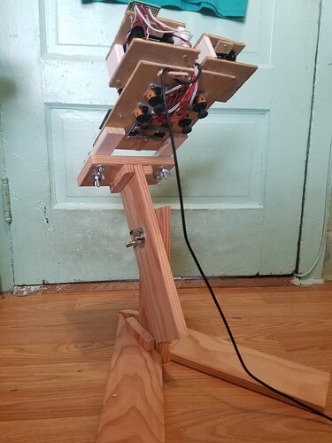
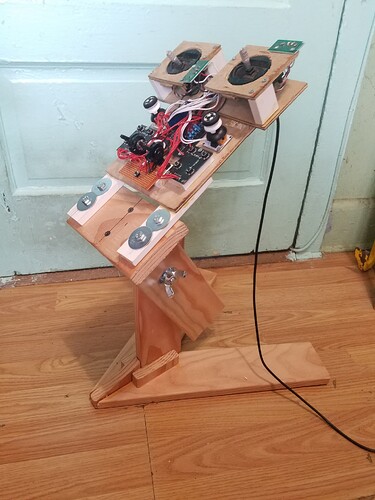
The project is "completed" and in use. It is a game controller with a bunch of joysticks, for use in space games and other flight simulators and FPV simulators. It works well, except the connection to the pc is shaky. I don't know why, but it failsafes (an aspect of the vjoyserialfeeder app used to connect to the pc) a lot, forcing me to "disconnect" then "reconnect" in the app to bring it back.

Is it possible that the arduino is not running smoothly because I have too many loads on the 5v? If so what can I do? I have a similar project that is smaller, only 4 joysticks, and no additional potentiometers, it never has this problem. (sometimes I bump the usb connector, but it's a different situation, and it's just that I wore out the usb connector by now).

You can view the vjoyserialfeeder project (and it's code) here:


my specific sketch (by editing the one from vjoyserialfeeder) is here:

#include <CD74HC4067.h>

#include "ibus.h"


// //////////////////
// Edit here to customize

// How often to send data?
#define UPDATE_INTERVAL 10 // milliseconds


// 1. Analog channels. Data can be read with the Arduino's 10-bit ADC.
// This gives values from 0 to 1023.
// Specify below the analog pin numbers (as for analogRead) you would like to use.
// Every analog input is sent as a single channel.
#define NUM_ANALOG_INPUTS 16
byte analogPins[] = {0, 1, 2, 3, 4, 5, 6, 7, 8, 9, 10, 11,12,13,14,15}; // element count MUST be == NUM_ANALOG_INPUTS

#define NUM_OTHER_ANALOG 2

// 2. Digital channels. Data can be read from Arduino's digital pins.
// They could be either LOW or HIGH.
// Specify below the digital pin numbers (as for digitalRead) you would like to use.
// Every pin is sent as a single channel. LOW is encoded as 0, HIGH - as 1023
#define NUM_DIGITAL_INPUTS 13
byte digitalPins[] = {2,3,4,5,6, 7,8,9,10,11,12,13,A5}; // element count MUST be == NUM_DIGITAL_INPUTS


// 3. Digital bit-mapped channels. Sending a single binary state as a 16-bit
// channel is pretty wasteful. Instead, we can encode one digital input
// in each of the 16 channel bits.
// Specify below the digital pins (as for digitalRead) you would like to send as
// bitmapped channel data. Data will be automatically organized in channels.
// The first 16 pins will go in one channel (the first pin goes into the LSB of the channel).
// The next 16 pins go in another channel and so on
// LOW pins are encoded as 0 bit, HIGH - as 1.
#define NUM_DIGITAL_BITMAPPED_INPUTS 0
byte digitalBitmappedPins[] = {}; // element count MUST be == NUM_DIGITAL_BITMAPPED_INPUTS


// Define the appropriate analog reference source. See
// https://www.arduino.cc/reference/en/language/functions/analog-io/analogreference/
#define ANALOG_REFERENCE DEFAULT

// Define the baud rate
#define BAUD_RATE 115200

// /////////////////


#define NUM_CHANNELS ( (NUM_ANALOG_INPUTS) + (NUM_DIGITAL_INPUTS) + (NUM_OTHER_ANALOG) + (15 + (NUM_DIGITAL_BITMAPPED_INPUTS))/16 )

CD74HC4067 my_mux(A0, A1, A2, A3);
const int signal_pin = A4; // Pin A4 - Connected to Sig pin of CD74HC4067
IBus ibus(NUM_CHANNELS);

void setup()
{
  analogReference(ANALOG_REFERENCE); // use the defined ADC reference voltage source
  Serial.begin(BAUD_RATE);           // setup serial
  pinMode(A0, OUTPUT);
  pinMode(A1, OUTPUT);
  pinMode(A2, OUTPUT);
  pinMode(A3, OUTPUT);
}

void loop()
{
  int i, bm_ch = 0;
  unsigned long time = millis();

  ibus.begin();

  // read analog pins - one per channel
  for(i=0; i < NUM_ANALOG_INPUTS; i++) {
    //my_mux.channel(6);
    //Serial.println("-" + String(i));
    my_mux.channel(analogPins[i]);
    //int val = analogRead(signal_pin);
    //Serial.println("Channel "+String(i)+": "+String(val));
    ibus.write(analogRead(signal_pin));
   // Serial.println(String(analogPins[i]) + " - " + String(analogRead(signal_pin)));
   // Serial.println(analogPins[i]);
  // read digital pins - one per channel
  }
  ibus.write(analogRead(A6));
  ibus.write(analogRead(A7));
  for(i=0; i < NUM_DIGITAL_INPUTS; i++)
    ibus.write(digitalRead(digitalPins[i]) == HIGH ? 1023 : 0);
    //Serial.println("--" + String(i));
  // read digital bit-mapped pins - 16 pins go in one channel
  for(i=0; i < NUM_DIGITAL_BITMAPPED_INPUTS; i++) {
  	int bit = i%16;
  	if(digitalRead(digitalBitmappedPins[i]) == HIGH)
  		bm_ch |= 1 << bit;

  	if(bit == 15 || i == NUM_DIGITAL_BITMAPPED_INPUTS-1) {
  		// data for one channel ready
  		ibus.write(bm_ch);
      //Serial.println("--");
  		bm_ch = 0;
  	}
  }

  ibus.end();
  //Serial.println("end");
  time = millis() - time; // time elapsed in reading the inputs
  if(time < UPDATE_INTERVAL)
    // sleep till it is time for the next update
    delay(UPDATE_INTERVAL  - time);
}

Maybe I am missing something, but it seems that a 0 byte array is not very useful and will cause problems if you try to write anything into the array.

One first try is to exchange the USB cable into a new. Cables, contacts do get old. I see that when charging a phone. Any little touch and the charging is restarted. Low cost action to try a new cable.

I did. It really seems to have nothing to do with the cable. On my other smaller one,, I do bump the cable and it is what causes the disconnection. However,,,, this one is a pretty good cable with good wires also. I won't rule it out completely, but I feel pretty sure it shouldn't be the problem in this case. I do wish there was an easier way to just solder the leads to the arduino, but I would need to use an ftdi for that, it's complicated, not too bad, but also means buying stuff. If I could just cut a wire and then solder to the arduino, but there's no nice place for it. I don't think soldering to the usb port connectors will be durable.

its just the easiest way to leave the code as it is. I didn't make the code, I just adapted with the least possible modification.

I can't imagine that would cause it to failsafe/lose connection though?

If possible cause suggested by one of the experts, perhaps you need to expand your imagination.

nothing should be being tried to be written into the array, and it works the whole time. The issue is that it loses connection stability

One indication of writing or reading beyond the bounds of an array is random processor resets.

1 Like

I used angled DuPont pins and a strip of protoboard to which button cables are soldered. Those toy test cables with rounded males are not really suitable.

Maybe its a power issue. Try running the Arduino from an external power supply.

Wow thats an impressive project:

I'd suggest
1: tidy up the wires

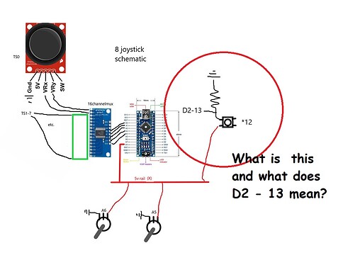
2: your buttons are wired with pull downs - but you havent shown the value.
They would be better wired connected to ground, using the arduino's internal pull-ups.

3: you havent shown the resistance of the joysticks (or a link to the parts used)

4: I dont see any decoupling.

they're 10k. I was under the impression there wasn't such an internal pull up option, at least with the nano? So I would run a wire from the nano, to the button, then to ground. I feel like I would have seen this elsewhere by now, in a tutorial or something. perhaps it is a newer feature?

I don't know where I should expect to put decoupling? I'm not very knowledgeable.

most of the sticks are also 10k. The big sticks are 5k, as are the wipers.

yes,, the wires are all over the place, but I've really reworked the solder joints a lot, and feel pretty good about every contact and that the wires also have good integrity.

I am reassured by so very many that a motherboard usb 5v should be more than adequate for any number of potentiometers on a thing like this, but I am wondering if perhaps my issue is not the power coming from the computer, but instead there is a regulator before the 5v rail, and my issue is from the load after this regulator, if indeed it does exist??

There is a regulator but because the arduino is being powered via USB, it’s not going through the regulator. If the pots need 5 volts then they should get that from an external source. Just make sure the ground of that external source is connected to the arduino ground too, otherwise you may get weird results.

Reasons not to use switches conected to the + supply:

decoupling refers to capacitors placed across the supply rails to prevent sudden changes in supply voltage.

Well, there is.

Hi,
What is this circled?

Can you please post a picture of a hand drawn circuit in jpg, png?
Hand drawn and photographed is perfectly acceptable.
Please include ALL hardware, power supplies, component names and pin labels.
It will be easier for you and easier on us.
I cannot see any supply or gnd to the multiplexer.

Thanks.. Tom.. :smiley: :+1: :coffee: :australia:

there's the same 5v and gnd to the mux as everything else.

D2-13 are pins on the nano, and that's the basic button diagram that goes to each of them.

Hi,
How are you powering your project?
Do you have a DMM?

What do you get when you measure the voltage between the 5V pin and gnd pin on the Nano.

What is the resistance of the pots in the joysticks?

If you are using the USB power, how long is the USB cable?

Thanks.. Tom.. :smiley: :+1: :coffee: :australia:

HOW you connect the ground to the mux will affect your readings. The grounds for the inputs (your 8 joysticks) and the mux and nano should be a star point.

However thats unlikely to cause your issue.

Can you run a MUCH simpler sketch to see if it still failsafes? Omit all the analog readings.

4.9v from 5v to gnd, but 4.6 at vin.?

my other project is 4.6 everywhere.