Please post your full sketch here to avoid teh need to visit another site, using code tags when you do
Posting your code using code tags prevents parts of it being interpreted as HTML coding and makes it easier to copy for examination
In my experience the easiest way to tidy up the code and add the code tags is as follows
Start by tidying up your code by using Tools/Auto Format in the IDE to make it easier to read. Then use Edit/Copy for Forum and paste what was copied in a new reply. Code tags will have been added to the code to make it easy to read in the forum thus making it easier to provide help.
It is also helpful to post error messages in code tags as it makes it easier to scroll through them and copy them for examination
I have modified the code, I tried the same exact code too, it doesn’t work, I’m using arduino nano “not original”
I tried the guy method of calibration, it’s still waaay off, I made one manually, still the same, the weird thing is, i tried the same exact code and the same schematic, but it’s still wrong.
I tested the PCB, I changed the resistors to 1% Tolerance, and tested each one by fluke multimeter.
You can split your code and post each section in a separate reply.
I've compiled your code for a Nano and this is the result:
Sketch uses 28972 bytes (94%) of program storage space. Maximum is 30720 bytes.
Global variables use 757 bytes (36%) of dynamic memory, leaving 1291 bytes for local variables. Maximum is 2048 bytes.
Next I noticed
Using library Adafruit SSD1306 at version 2.5.15 in folder: C:\Users\bugge\OneDrive\Documents\Arduino\libraries\Adafruit_SSD1306
That library uses dynamic memory allocation and requires 1 kB for the display. So your total RAM usage is 1781 bytes which will get you in the danger zone; I wonder if your problem is not a result of running out of memory (not sure though).
Lastly I noticed the use of an uninitialised variable:
C:\Users\bugge\AppData\Local\Temp\.arduinoIDE-unsaved2025619-22504-1sjryad.ro39\sketch_jul19a\sketch_jul19a.ino: In function 'GetESR':
C:\Users\bugge\AppData\Local\Temp\.arduinoIDE-unsaved2025619-22504-1sjryad.ro39\sketch_jul19a\sketch_jul19a.ino:5380:53: warning: 'cap_val_nF' may be used uninitialized in this function [-Wmaybe-uninitialized]
     sumvolt[2] -= (1745098UL*MAX_CNT) / (cap_val_nF * (cap_val_nF + 19));
                                                     ^
C:\Users\bugge\AppData\Local\Temp\.arduinoIDE-unsaved2025619-22504-1sjryad.ro39\sketch_jul19a\sketch_jul19a.ino:5182:17: note: 'cap_val_nF' was declared here
   unsigned long cap_val_nF"C:\\Users\\bugge\\AppData\\Local\\Arduino15\\packages\\arduino\\tools\\avr-gcc\\7.3.0-atmel3.6.1-arduino7/bin/avr-objcopy" -O ihex -j .eeprom --set-section-flags=.eeprom=alloc,load --no-change-warnings --change-section-lma .eeprom=0 "C:\\Users\\bugge\\AppData\\Local\\arduino\\sketches\\0B78D4AE6A2CBBF53E4B5904306DE410/sketch_jul19a.ino.elf" "C:\\Users\\bugge\\AppData\\Local\\arduino\\sketches\\0B78D4AE6A2CBBF53E4B5904306DE410/sketch_jul19a.ino.eep"
;
I saw videos on them they work, but dude, I’m 100% sure the PCB wiring is correct, I tested each trace, and all traces are wide enough and thick to not make any problems.
I’m trying to solve this problem from months, like tried everything, even used chatgbt, curses AI
And wrote code to be sure all wiring is correct, and they passed
I took a quick look at the code, and it has a lot of issues. For me, the non-starter is the use of goto, but the lack of modular organization, unneeded comments, and wasted space are issues too. I have seen a lot worse but a long time ago, this may be the new current champ though.
Good luck, and I will make a small wager on the PCB being the problem just because the OP is so dam confident it isn't. Yes, I am a contrarian!
Glad to see you are open to input. However, a breadboard, even the good ones, is extremely unreliable. If you want to go that route, only breadboard a small part of the circuit at a time and test. But even if all goes well, you are not positioning wires(traces) at the same distance and/or orientation, which can cause crosstalk.
I am a little surprised there is not a piece of software or perhaps hardware/software to test a PCB for crosstalk. I have several component testers, but not one of them is an ALL components. Maybe there is a reason for that?
At the very least start with creating 'helper' modules to isolate sections of code.
However, at this point you don't know if your issue is hardware or software. I am trained in both fields as a former IBM hardware/software engineer. It was a long time ago and isn't directly useable today, but I am very suspicious that you are experiencing cross talk. All the tests you did were for components, now you need to do either a full factorial test which for this size project could take a VERY long time, or at least do 'pairwise' testing. There are online/tools that will help you generate all the Pairwise combinbations.
If I have not been clear, I think there is a decent chance two traces running beside each other is the problem. They need to be rerouted so they cross at 90 degrees. As a last resort, do a breadboard with shielded wires, or maybe a intelligent sub-set of the wires. If you can reduce the hardware and software to a single component test failure like the Resistor test then the time and $ will be greatly reduced.
@anon543
Why is there a "power" LED using Nano pin A3 when the Nano has a built-in power LED? It seems the author cared more about bells and whistles than function.
The "fritz" and the schematic are not the same.
Were the PCBs made from the "fritz" or the schematic, or a totally different drawing not yet disclosed?

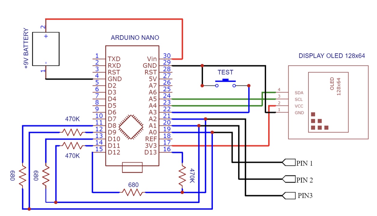

 now you made me feel there is something wrong there..
 most wires run togethers..