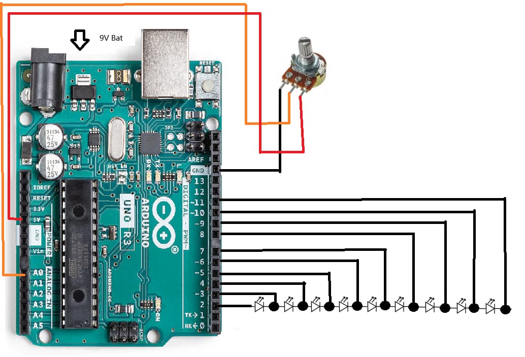
My Kid is now learning Arduino, he got a new Uno R3 starter Kits, and after I show him the example code of "LED Bar Graph", he played with the LEDs and give me a new design, and I couldn't explain how it works like that.
If there are no current limiting resistors for the LEDs, as the diagram indicates, you can expect the port output pins to fail, sooner or later. The LEDs may fail sooner.
The rule for that Arduino is that the output pin current should not be allowed exceed 20 mA, which also happens to be the maximum safe current rating for most common LEDs.
Judging from the brightness in the video, the LEDs are in the process of burning out.
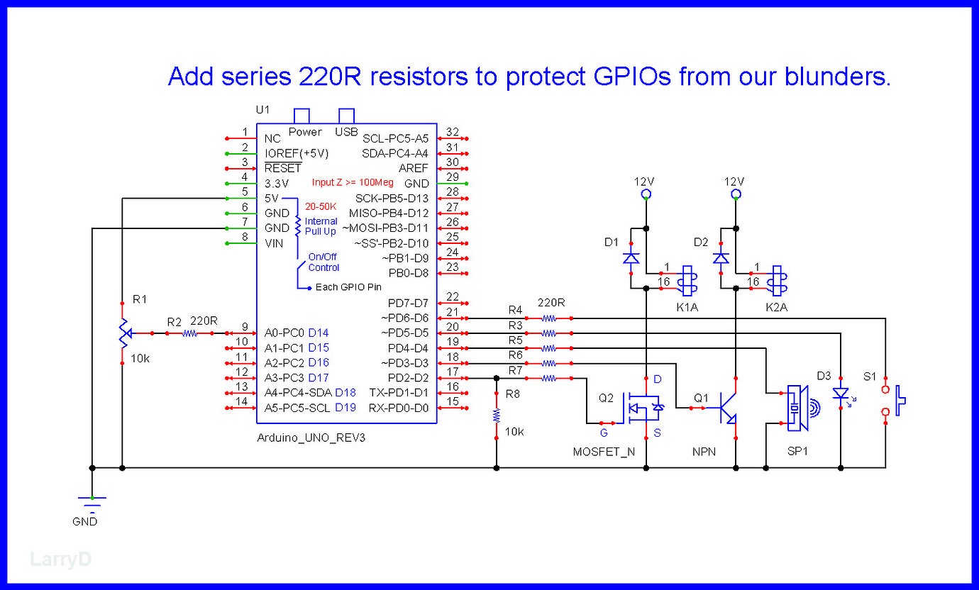
As mentioned, common LEDs require current limiting, add a series resistor on each LED.
Or, buy a new Arduino soon. ![]()
When a GPIO is LOW, there would be 0V on one side of a LED, a GPIO on the other LED pin set to a HIGH, turns ON the LED.
As well as all the other good advice you have got here, if you want an explanation of how it is actually working we need to see the code you are using.
You might want to look at this How to get the best out of this forum before you proceed any further.
It will tell you how to post code on this forum.
One pin at a time is high while others are low.
Just add >100R resistor to every pin, and you cam play safely
What is your question?
Unless the board came pre-loaded with the sketch, someone must have loaded it and has had sight of the code and an idea how it works.
It's all very well getting a row of LEDs to light up to get the interest going, but it's a fairly complicated point to start at and needs an understanding of analogue inputs and digital outputs.
Maybe turn all the LEDs on and vary the brightness would be a step forward.
There's no way to do that with that circuit.
Thanks, I know.
Adding a switch shouldn't be too much of a challenge.
They've already got the potentiometer in place.
It was just a thought.
This is certainly the way the circuit appears to have been drawn although it is not the obvious way of connecting multiple leds to an arduino.
Since only one led is lit at any one time, the circuit could be restructured so all the leds cathodes are joined together and that common cathode could itself be joined to the ground power rail via a single say 330 ohm current limiting resistor.
code is the example code
lots of comments, OP seems MIA...
Ah, ok.
And you are wearing blue socks today, correct?
Where is it?
We want the code you are actually using. My post #4 showed you what to read to tell you how to post code.
Search terms: arduino example code bar graph at DuckDuckGo
First link: https://docs.arduino.cc/built-in-examples/display/BarGraph/
OK. Looking at that it is now clear that what appeared in the OP was not exactly a "Bar Graph" and more of a single position indicator, which of course also has its uses. In a real bar graph, say a VU meter or similar, multiple leds are on to form a bar whereas that in the OP could show only one led at a time.
If you set first pin high, second one high impedance and third low, it would likely give LEDs on-on-off... (repeated 3 times).
Still waiting for you to post the code that was used. Why are you so reluctant to do this?
If you want help you have to cooperate.
I’m still unclear about OP’s real question…
He want's to be able to understand how the code works in the way it does. But without seeing the code he is using I for one will not even try at an explanation, unlike some others reckless guess from other posters.