Nano 33 and 8 channel relay module unwanted startup activation

Hello everyone,

After going through some trouble with the relay module (and 74HC595) I finally have it working. Now I want to get it working with the IOT Cloud, and am running into a hurdle again.

When the Nano 33 IoT loads a new sketch or restarts all 8 relays switch on and off (once) in the blink of an eye. The relay module switches on with LOW, and stays off with HIGH. I've tried all the things I could find in other topics but nothing has worked so far, and I'm at my wit's end :frowning:

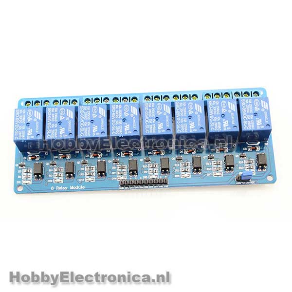
The OE pin is tied to ground, and so is the latch with a 10K resistor. There is a 0.1 uF cap over VCC and GND and the 595 is powered with it's own power supply. I've tried connecting the relay module directly to the arduino, or with isolated power supply like this picture. For that I've soldered the 2 contacts on the undersude to get 5V from the USB to the 5V pin on the nano.

I've tried setting the pinModes in setup to high but it doesn't help. At some point the relay module just started going nuts on/off continuously untill I pulled the power. I think this might be related to the power from the USB-5v pin. edit: or not because it also happens when uploading a sketch while powered externally.

Is there something I'm overlooking or is this a result of the way it's wired?

/*
  bool relay1;
  bool relay2;
  bool relay3;
  bool relay4;
  bool relay5;
  bool relay6;
  bool relay7;
  bool relay8;
*/

#include "thingProperties.h"

#define dataPin 4   //SER serial Input
#define latchPin 5 // Register Clock/Latch
#define clockPin 6 // SRCLK Shift Register Clock
byte relays = 0;  // Variable to hold the state of relays in a byte

void setup() {

  Serial.begin(9600);
  delay(1500);

  initProperties();
  ArduinoCloud.begin(ArduinoIoTPreferredConnection);
  setDebugMessageLevel(2);
  ArduinoCloud.printDebugInfo();
  
  //pinMode(dataPin, HIGH);
  //pinMode(latchPin, HIGH);
  //pinMode(clockPin, HIGH);
  
  pinMode(dataPin, OUTPUT);
  pinMode(latchPin, OUTPUT);
  pinMode(clockPin, OUTPUT);
  resetAllRelays();
  ArduinoCloud.addCallback(ArduinoIoTCloudEvent::SYNC, reset); //reset dashboard buttons
}

void loop() {
  ArduinoCloud.update();
}


void updateShiftRegister() {
  digitalWrite(latchPin, LOW);
  shiftOut(dataPin, clockPin, LSBFIRST, relays);
  digitalWrite(latchPin, HIGH);
}

void reset() {
  relay1 = false;
  relay2 = false;
  relay3 = false;
  relay4 = false;
  relay5 = false;
  relay6 = false;
  relay7 = false;
  relay8 = false;
}

void resetAllRelays() {
  digitalWrite(latchPin, LOW);
  shiftOut(dataPin, clockPin, LSBFIRST, 0b11111111);
  digitalWrite(latchPin, HIGH);
}

void onRelay1Change()  {
  if (bitRead(relays, 0) == 0) {
    //Serial.println("on");
    bitWrite(relays, 0, 1);
  } else {
    //Serial.println("off");
    bitWrite(relays, 0, 0);
  }
  updateShiftRegister();
}

void onRelay2Change()  {
  if (bitRead(relays, 1) == 0) {
    bitWrite(relays, 1, 1);
  } else {
    bitWrite(relays, 1, 0);
  }
  updateShiftRegister();
}

void onRelay3Change()  {
  if (bitRead(relays, 2) == 0) {
    bitWrite(relays, 2, 1);
  } else {
    bitWrite(relays, 2, 0);
  }
  updateShiftRegister();
}

void onRelay4Change()  {
  if (bitRead(relays, 3) == 0) {
    bitWrite(relays, 3, 1);
  } else {
    bitWrite(relays, 3, 0);
  }
  updateShiftRegister();
}

void onRelay5Change()  {
  if (bitRead(relays, 4) == 0) {
    bitWrite(relays, 4, 1);
  } else {
    bitWrite(relays, 4, 0);
  }
  updateShiftRegister();
}

void onRelay6Change()  {
  if (bitRead(relays, 5) == 0) {
    bitWrite(relays, 5, 1);
  } else {
    bitWrite(relays, 5, 0);
  }
  updateShiftRegister();
}

void onRelay7Change()  {
  if (bitRead(relays, 6) == 0) {
    bitWrite(relays, 6, 1);
  } else {
    bitWrite(relays, 6, 0);
  }
  updateShiftRegister();
}

void onRelay8Change()  {
  if (bitRead(relays, 7) == 0) {
    bitWrite(relays, 7, 1);
  } else {
    bitWrite(relays, 7, 0);
  }
  updateShiftRegister();
}

Also, what's bothering me is the sketch in IDE is different, but the code would not work with IoT

This is running with IDE, without the startup blink of all the relays:

const int latchPin = 5;  // Latch pin of 74HC595 is connected to Digital pin 5
const int clockPin = 6;  // Clock pin of 74HC595 is connected to Digital pin 6
const int dataPin = 4;   // Data pin of 74HC595 is connected to Digital pin 4

byte leds = 0;  // Variable to hold the pattern of which LEDs are currently turned on or off

void setup() {
  // Set all the pins that control 74HC595 as OUTPUT
  pinMode(latchPin, OUTPUT);
  pinMode(dataPin, OUTPUT);
  pinMode(clockPin, OUTPUT);
  Serial.begin(9600);
}

void loop() {
  if (Serial.available() > 0) {
    int number = Serial.parseInt();
    Serial.print("Relay ");
    Serial.print(number);
    Serial.print(" is now ");
    if (bitRead(leds, number) == 0) {
      Serial.println("on");
      bitWrite(leds, number, 1);
    } else {
      Serial.println("off");
      bitWrite(leds, number, 0);
    }
    updateShiftRegister();
  }
}

void updateShiftRegister() {

  digitalWrite(latchPin, LOW);
  shiftOut(dataPin, clockPin, LSBFIRST, ~leds);
  digitalWrite(latchPin, HIGH);
}

It has bothered me that on the IDE sketch I'm inverting the byte, but on the cloud sketch that didn't work.

i would not take one single relay module to cap power of "8-way"-module before initialisation.
i would not use additional NPN or N-channel transistors to invert logic.
i would cut wires on module PCB and make it active HIGH.

is that possible with this module?

I've seen this module advertised with HIGH/LOW setting but I take it the "level trigger" is not the same as HIGH active?

they are mostly made like this


remove jumper.
desolder resistor R1/R4/... or cut wires between them
grond all IN pins
connect +power to "ry-vcc"
anods of opto with resistor(you may replace LED or take one additional) connect to outputs of 595 IC.


cut copper at place shown in red
strip some copper where S2/S4-S8
595 IC Q0-Q7 output pins to S1-S8
remove jumper
all input pins solder to GND
+5v to JD-VCC
arduino GND to GND

Show us the schematic of this.

If you make the relays active high they will turn on when you reset your Arduino. The active low solves this problem. When using MOSFETs most add a pull down resistor to guarantee the relay state until setup gets control. You can use the OE\ and turn it low when everything is set, that will enable the shift register to assert its outputs.

why you think so? and anyway 595 will not go HIGH spontaneous even if all arduino pin while reset will do

I'm not familiar with a site or program to make a schematic, and the 3 or 4 I tried didn't have a 74HC595 in them so I'll link you to my wokwi, sorry about that. Also the led in the drawing represents a 0.1 uF capacitor.

The main thing that has me stumped is the difference that an IDE sketch does not trigger an unwanted activation, and the sketch from my IoT thing does. I'm trying to make them more similar to see if I can eliminate the source but no luck so far.

Connect the 595 OE to an Arduino pin, make OE HIGH at power up/reset time (disabling the 595 outputs).

After sending the relay levels to the 595, make OE LOW to operate the relays as per what you sent.


Does your red LED have a resistor ?

I'll try with the OE pin, but I don't know if I have a pin to spare in the final project. It's the main reason I'm using the 74HC595.

The LED does not have a resistor as it is not really a LED, but a cap. I could not find how to add a cap in wokwi so I used a LED and tried to describe it wasn't, sorry about that.

why you place resistor between arduino GND and other GND ?

At first, when the Nano would reboot or load a new sketch all the relays would flicker on/off a lot for about a second. It was suggested here that I use a 10K pulldown on the latch to get of this event. And it did. Everything worked perfectly then when I was using the IDE sketch. When I tried to move it to the Cloud IoT I encountered the new problem of everything clicking just once.

try external pull up resistor to /OE
and same to input pins of relay module.

If you do not have a spare Arduino GPIO:

  • Connect OE to 5V thru a 10uF capacitor.
  • Connect OE to GND thru a 10 to 56k resistor.

In setup( ), immediately send the relay byte to the 595.

The above makes the 595 OE disabled when power is applied.
While the OE is disabled, you send your 8 bit relay byte to the 595.
When the 595 OE settles to 0v (10uF cap is fully charged), the 595 output pins will have their levels set up for the relay card (LOW true).

You can also place a reversed biased 1N4148 across the 10uF capacitor to provide a discharge path at power down.

See image in post #24

Thank you @LarryD, I will give this a try. ( and learn to understand the whole thing better. )

At the moment I'm worried I've damaged the nano or the relay module. Or any of the parts for that matter. Sometimes on a boot or upload it goes off like a machinegun, and sometimes it doesn't. I was allmost sure I eliminated the issue, and then it's back with a vengeance.

With isolated powersupply across the relayboard the LED's only light up about 50-60%, there is no longer a click sound and there is a slight hum from the LED/relay going active.

In the configuration shown in post #17, the external power supply powers the relay coils, not the LEDs.

The LEDs get their power from the Arduino 5v supply; the GND for the LEDs is from the 595 outputs.

Show us your actual wiring of schematic #17.

the VCC next to the relay inputs is powered by the 5V pin from the Nano 33 IoT. I've soldered the 2 plates at the bottum to get USB power to the pin.

I'll update the wokwi, or make a new one when I get home in a bit.