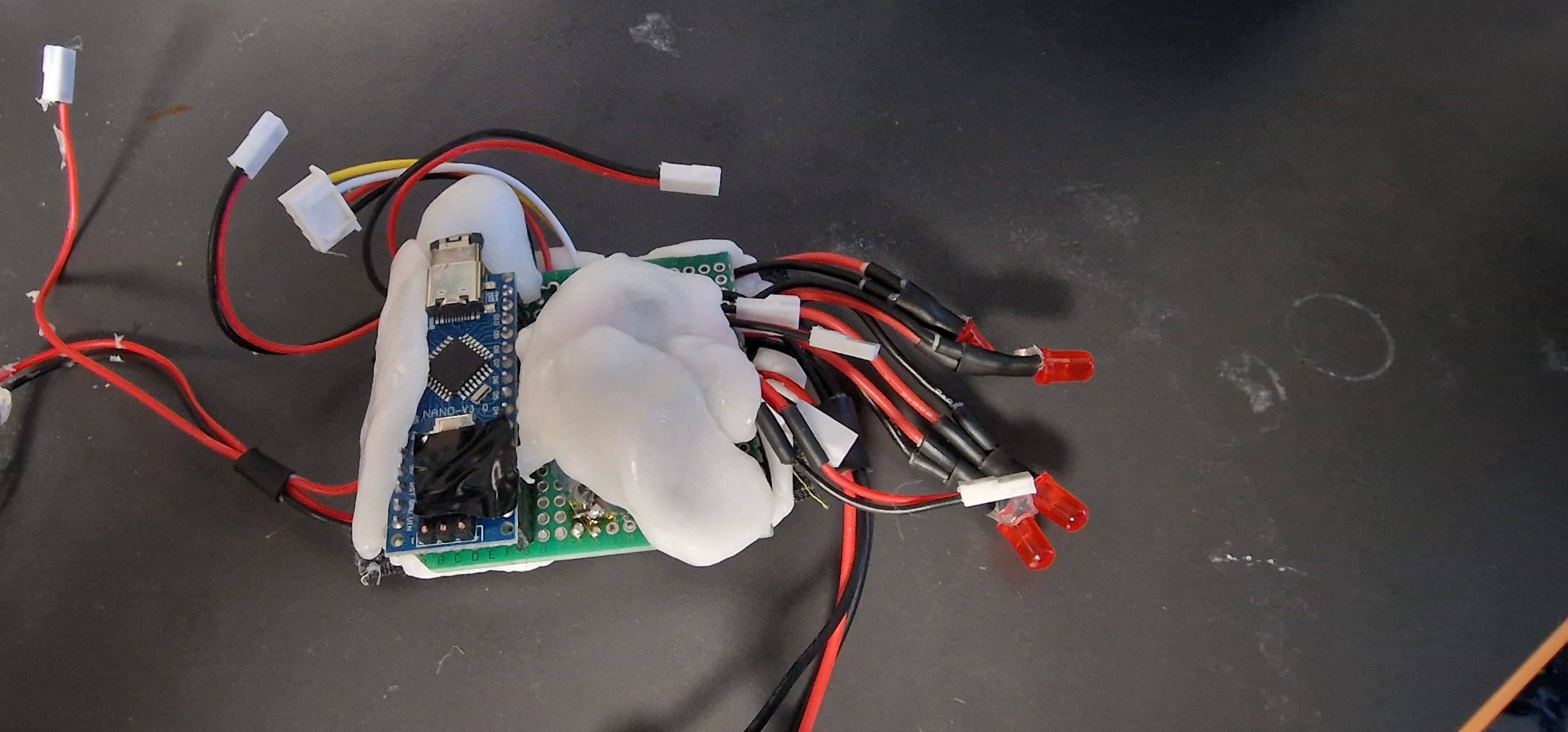
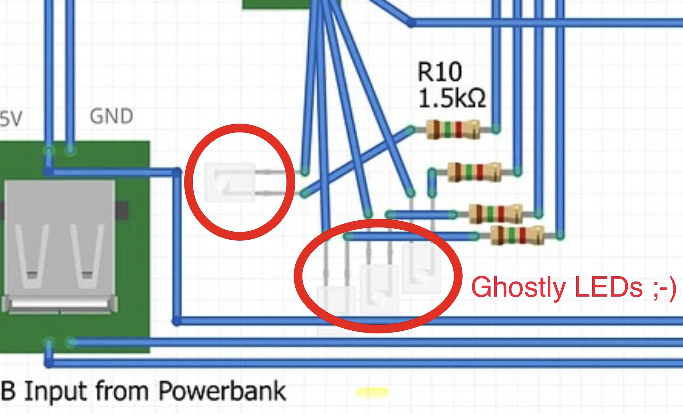
the following schematic shows the electronics I have built for a costume. It's meant to give me PWM control over four LED Filaments (power draw about 40mA each) as well as two tiny (30mm) PWM fans (which are wired in parallel).
That second set of LEDs at the bottom are just for info display inside the costume, meant to glow very weak, hence the 1.5k resistors.
Input is a microphone module and two buttons. Am using the built-in resistors of the Nano for those.
The power supply is an USB powerbank. It goes into that female USB board and there's also a male USB connector which then goes into the arduino (maybe this is weird? Thought that's the easiest way to ensure that I can still reprogram the IC while in circuit).
The LEDs, fans and even the microphone etc. are all wired to that input board -> no large power should therefore actually go through the arduino board itself (I believe at least). Am not using the 5V or 3.3V pins of the nano after all. I even avoided using its GND pins for anything except for the buttons.
The Arduino is grounded through the USB connector.
To my own surprise it all worked immediately... for a couple minutes... until it fried.
The first time I was actually putting the costume on when it suddenly flickered up and down somehow (I was hearing the fans fluctuating) for a few seconds and then all shut off and I was smelling something burnt (since it's close to my face).
Thought however I made a short circuit myself by moving because some wires of the buttons were not isolated and possibly somewhat near the board.
Now I've replaced the Arduino Nano and isolated everything. When turning it on I even measured the powerdraw. Roughly 250mAh from the USB which is what I'd expect.
Yet this time after about 2 minutes of just laying around, it shut off again
The Arduino Nanos are completely dead in both cases. Even removing from the circuit and attaching to PC gives nothing. Not even the onboard LED is glowing.
However I cannot see any damage at all. No idea what smelled before...
Anyone have an idea what the cause could be?
Have I missed something critical?
Fear that is not feasible because it's all very compact and my attempts at isolation made it worse
Initially I had it in a neat case but that then didn't fit inside the costume q_q
Huh, interesting. I calculated the 1.5K to allow for about 2mA for those small LEDs. If I use 10k there, they'll probably not glow anymore.
Why exactly is the circuit problematic like this?
Is the Arduinio overloaded by driving the mosfets + 2mA for those extra LEDs or am I not allowed to think of the two things as being separate "consumers" from the Nano's pin (which is supposed to be fit for 20mA)?
I agree about the divider but not the solution. I suggest the solution is to connect the 1k5 resistors directly to the Nano output pins rather than the MOSFET gates. If you do this you may well find the LEDs are brighter, if this is the case then increase the values of the resistors accordingly.
Nothing I can see in your diagram is obviously going to cause a problem. I suggest:
Check very carefully for short circuits. If you don't have a multimeter then buy one for testing.
Check very carefully that everything is wired correctly.
Check the MOSFETs are connected correctly, it would be easy to get source and drain reversed.
Buy some freezer spray, power up the circuit and spray everything with freezer spray. Look for places where the frost either doesn't form or quickly melts. As you know it works for 2 minutes before dying maybe don't power for more than 30 seconds at a time.
I also agree that your circuit looks like it should not overload the Nano.
Since you are powering it through the USB socket, there are only limited possibilities for a catastrophic short circuit, say 5v to ground. The official Nanos https://content.arduino.cc/assets/NanoV3.3_sch.pdf have a polyfuse which would prevent a failure. Some clones may not have this protection and the (backfeed preventing) diode between VUSB and +5v will burn out.
The 4 wires to the USB plug into the Nano look odd though since you are using this for power only.
This may well be worth trying anyway even on a failed Nano because if the anti-backfeed diode has burned out, it will prevent only power from the USB socket getting through. The +5v pin should still function to power the device. But, then, even more care is required to prevent a future short circuit.
OH!
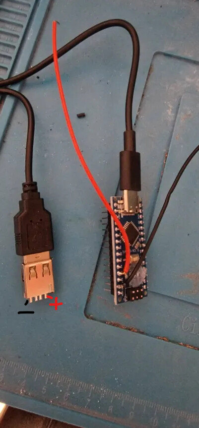
Yep, you hit the bullseye. Connecting power via the pins does turn the on-board LED on. Works on the extracted Nano as well as the one connected in.
Tried to run the whole circuit by connecting the 5V of the USB as well, and... Turns out there's a fat 6Ohm short circuit just across + and GND of my board still present >< (I should have measured just the input pins myself before but didn't think of something so trivial...)
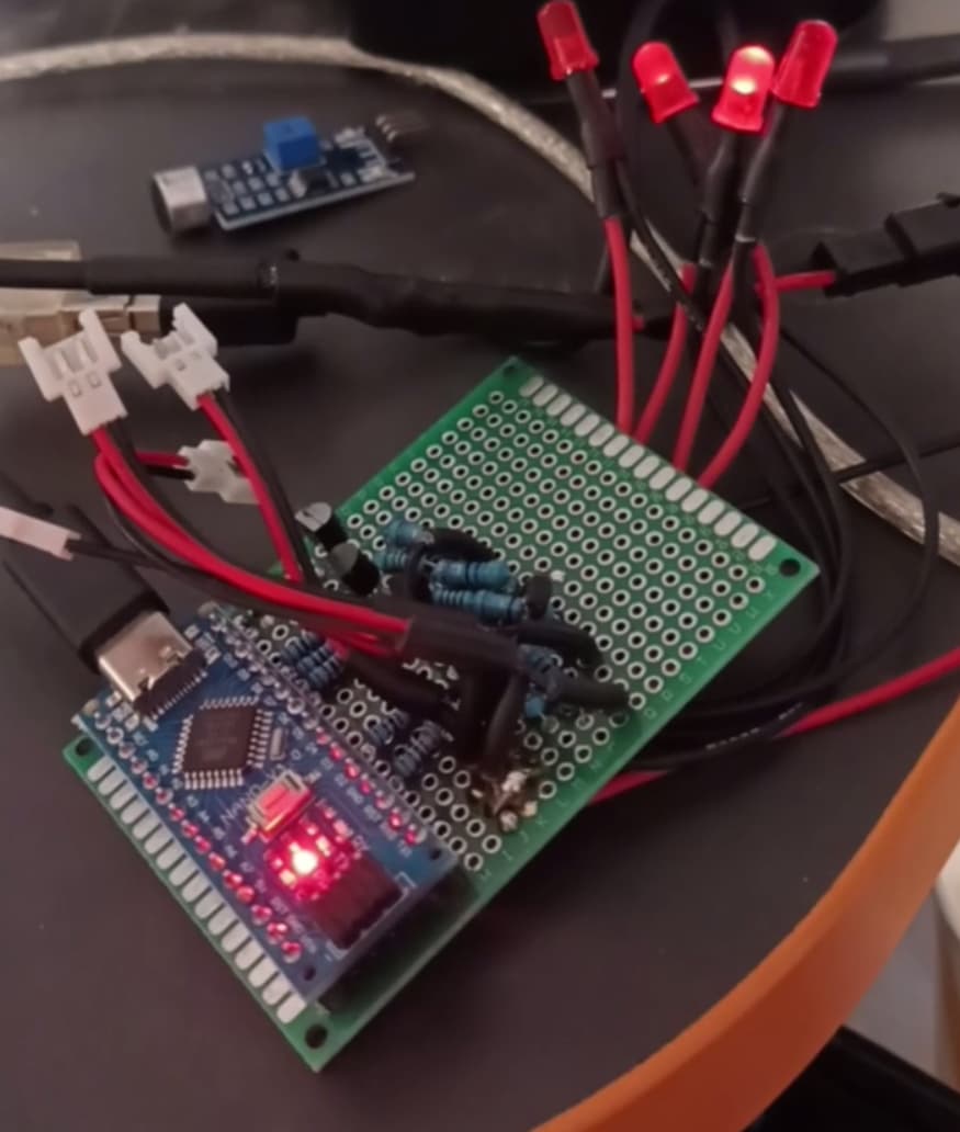
Must have happened during final assembly because I programmed the whole thing for hours while in the same connection state like right now (that was the purpose of the "ghostly LEDs" so I can debug it on my desk outside the costume and yet test most features.
Yet it also worked for a short time between the first Nano and the second...
Oh well.
The plastic you see is essentially glued on now (it's "polymorph"). Not my smartest move but best if I start from scratch anyways to make this fit properly with a case...
I connected the primary data cables for the purpose of being able to program it after the fact and especially program it while connected to the curcuit.
If I were to power the LED filaments etc. through the same power that's connected to the 5V pin, what happens then when I connect the Nano's USB to the PC without detaching the circuit?
I assumed it would try to draw all the power (for the LED filaments and fans) through the board of the Nano (whatever is between the USB and the 5V pin), frying it that way, right?
Assuming there is external power on the +5v pin of the Nano at 5v with sufficient to power the fans and leds, then there will be no problem if you plug the USB cable into the Nano to program it. The actual power flowing through the Nano will be small because most periperals devices are powered by that external power source.
The voltage passing through the Nano will anyway be subject to a 0.3v drop because of the anti-backflow diode.
To be asolutely safe, you could put a jumper on the Nano's +5V pin and remove it when programming:
@gilshultz Thanks and yeah I should have done that.
Have identified the short circuit and it's NOT my wiring >< The Nano itself got a short circuit.
Even when taking it out of the rest, just standalone, an USB cable has a connection between GND and V+. Only the USB though. The Nano's own GND and V+ pins are not connected and that's why wiring it up that way makes its LED glow again etc.
Does that mean the small onboard power supply is fried?
If so I'm assuming that's just the symptom and not the original cause of my problems...
What can cause that to happen if I have never used the V+ of the Nano's pins for anything?
Will be getting some freezer spray to do that identification method of what part is actually shorted. Thanks for the idea @PerryBebbington
Btw. I've read somewhere one should put a diode in line when powering motors. Is that a thing? If so, does it need to be on the PWM pin, or the supply?
I don't fully understand your description of the circumstances under which this "short circuit" manifests itself so I'll just answer this point:
It is usual to use a flyback diode, reversed across the terminals of a DC motor, to suppress electrical noise. This is in parallel (NOT inline) with the motor. Ensure the polarity is correct to avoid (another) short circuit.